HomeServerBlog optical access planner
BiDi Fiber Wavelength Planner Calculator
Plan single-fiber BiDi wavelength direction, strand savings, link count, pair orientation, channel plan spacing, connector loss, reach limit, optical margin, and spare fiber capacity before ordering matched optics.
1BiDi wavelength presets
2Wavelength, fiber, and loss inputs
BiDi calculation breakdown
Planner verdict
3Live wavelength, pair, fiber, and loss cards
Large enough separation helps the BiDi filters isolate transmit and receive paths.
Compares single-fiber BiDi links against traditional duplex fiber links.
Fiber attenuation, connector insertion loss, channel penalty, and splice allowance.
Estimated reach if the current connector stack and reserve are kept unchanged.
4Optic pair comparison grid
5BiDi wavelength tables
Common BiDi wavelength pair orientation
| Pair family | Endpoint A optic | Endpoint B optic | Planning note |
|---|---|---|---|
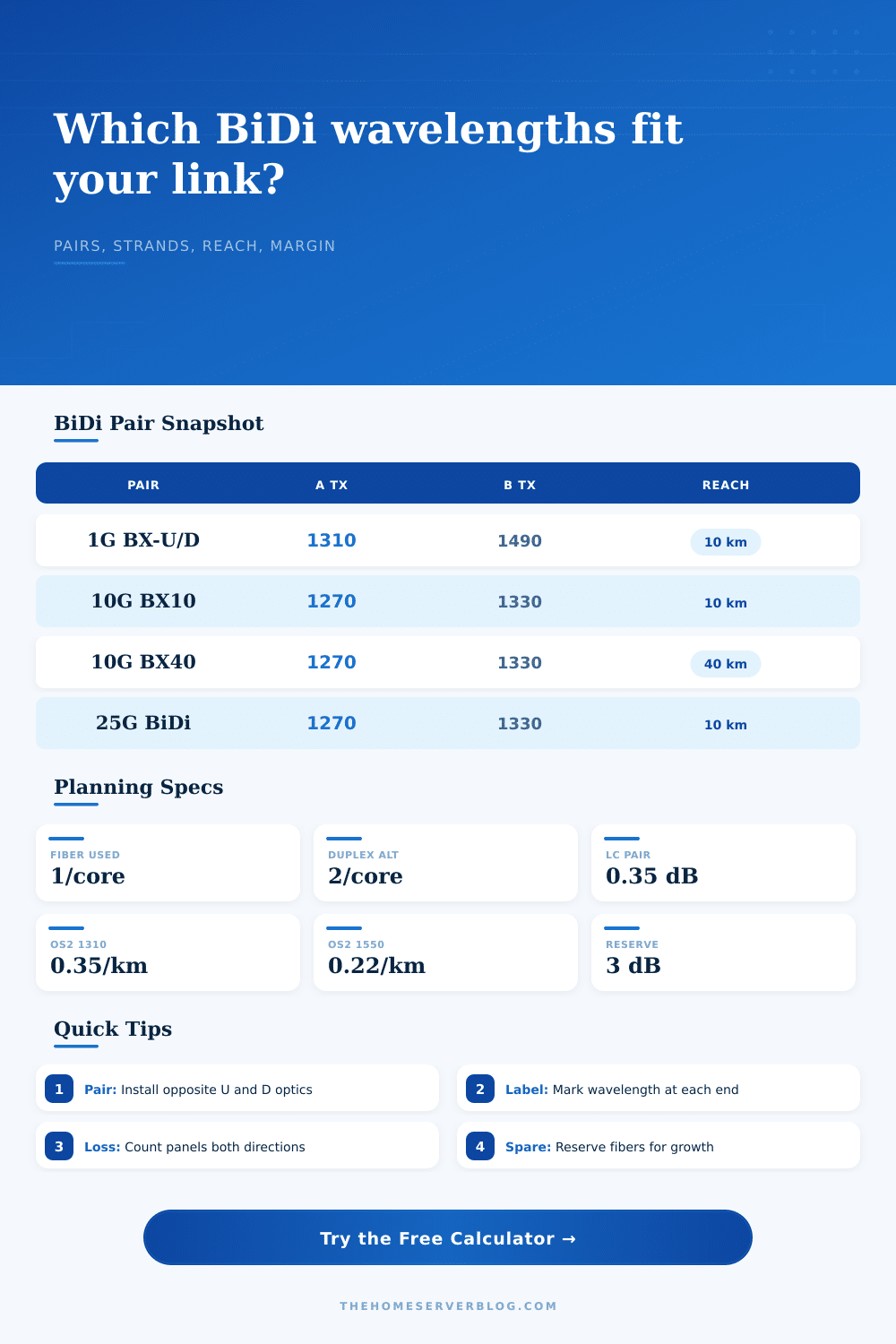
| 1G BX-U/D | 1310 Tx / 1490 Rx | 1490 Tx / 1310 Rx | Common access pairing; labels vary by vendor, so verify Tx and Rx wavelengths. |
| 10G BX10 | 1270 Tx / 1330 Rx | 1330 Tx / 1270 Rx | Typical short single-mode SFP+ BiDi pair for one strand. |
| 10G BX40 | 1270 Tx / 1330 Rx | 1330 Tx / 1270 Rx | Same wavelength pairing with stronger optics and stricter link margin. |
| CWDM BiDi | 1470 Tx / 1490 Rx | 1490 Tx / 1470 Rx | Useful when many single-fiber services share a wavelength inventory. |
| Long C/L split | 1550 Tx / 1570 Rx | 1570 Tx / 1550 Rx | Lower fiber attenuation but more bend and filter discipline at the edge. |
BiDi strand count planning
| Active links | BiDi fibers | Duplex fibers | Why it matters |
|---|---|---|---|
| 1 link | 1 strand | 2 strands | One spare strand can become a future full-duplex service. |
| 4 links | 4 strands | 8 strands | Good fit for small home lab uplink bundles or floors. |
| 12 links | 12 strands | 24 strands | Can avoid pulling a second 12-fiber trunk for the same link count. |
| 48 links | 48 strands | 96 strands | Useful in constrained conduits, risers, and campus paths. |
Wavelength loss planning values
| Wavelength band | Typical attenuation | BiDi use | Planning caution |
|---|---|---|---|
| 1270 to 1330 nm | 0.35 dB/km | 10G and 25G BiDi access optics. | Works well on OS2; check dispersion and reach class. |
| 1310 to 1490 nm | 0.35 / 0.25 dB/km | 1G BX and PON-like directional plans. | Respect coexistence filters if sharing with PON plant. |
| 1470 to 1530 nm | 0.28 dB/km | CWDM BiDi pairs and passive color shelves. | Confirm passive filter passband and channel isolation. |
| 1550 to 1610 nm | 0.22 to 0.25 dB/km | Longer single-mode BiDi and CWDM edge channels. | Bend loss and receiver overload checks become more important. |
Loss budget checkpoints
| Item | Typical value | Planner use | Field check |
|---|---|---|---|
| Clean LC pair | 0.25 to 0.35 dB | Default connector pair allowance. | Inspect and clean before measuring margin. |
| Patch panel path | 2 to 4 pairs | Front and rear adapter faces can double-count quickly. | Trace every mated pair end to end. |
| Fusion splice | 0.05 to 0.10 dB | Reserve for closures or repairs. | Use measured splice loss when documented. |
| Design reserve | 2 to 4 dB | Held back after calculated loss. | Keep enough headroom for future patches. |
6BiDi pair and channel plan reference
| Channel plan | Good wavelength separation | Use case | Compatibility note |
|---|---|---|---|
| Standard BX | 40 to 180 nm | Simple Ethernet BiDi pairs without passive mux shelves. | Install one upstream and one downstream optic, not two of the same label. |
| CWDM adjacent | 20 nm | Color inventory where adjacent CWDM wavelengths are intentionally paired. | Filter isolation matters more; use matched optics from the same plan. |
| Wide split | 160 to 240 nm | 1G access, PON-like, or custom lab links using separated bands. | Great isolation, but loss can differ by direction. |
| PON coexistence | Vendor-defined | Shared passive plant with 1310, 1490, 1550, or 1577 nm services. | Do not assume spare wavelengths are safe on live provider plant. |
| Custom lab | 20 nm or more | Controlled links, test filters, and educational optical benches. | Measure both directions before treating it as production capacity. |
7Two BiDi planning tips
Perhaps you have 12 strands of single-mode cable in a rack or a lab but just 4 active connection? The temptation would be to run two strands per connection and go from there. That’s the duplex way. If you’re constructing a small campus or lab environment, though, you may wish to look at using bidirectional optics. These allow you to send two-way traffic over a single strand. The math are very different.
How to Pair Wavelengths Counting Strands This is where the calculator on the page come in. You won’t have to guess whether you have enough optical budget to get through a tight bend or two or three dirty connectors. Enter your distance, your number of connectors, your type of fiber, and it will tell you yes or no; do I fit? But more importantly, it will tell you how much room you’ll have after the fact when that fiber gets old and dirty.
Why You Should Use the Fiber Calculator Tool
What’s important to understand about bidirectional is that it’s not magic. It’s two different color lights in the same pipe. One end emits at 1270 nanometers, and receives at 1330. The other do the reverse: emits at 1330 nanometers and receives at 1270. Get those mixed up, and you’re basically yelling through a wall. But the tool makes you clearly state what those emit/receive wavelengths are. It doesn’t just assume you know which SFP plugs into each end. This is a good thing.
You’ll go to racks and find that people has grabbed two transceivers that look exactly the same out of the drawer. They then plug them both into the same side of a link, and then they get silence. The calculator saves you from that because it won’t let you overlook how the pair is oriented until after you’ve seen the loss budget.
Oh and then there’s attenuation. Fiber is not a wire. Fiber is a medium that eats signal. It eats signal. Specifically, it eats shorter wavelength signal (like 1310 nanometers) more than longer wavelength signal (like 1550). The calculator takes this into account using attenuation coefficient specifically depending on which kind of transceivers you’re choosing. It also includes connector loss.
Most folks trip up here. Connectors are the first thing you think about and you tend to assume they’re zero-loss connectors. Nope. A simple LC connector can take away 0.35 decibels. Six connection points equals more than two decibel gone before light ever touches any fiber.
Why do I need to bother using a design margin for the link? Why can’t I just build the link out to the very limit of my receiver’s sensitivity?” In the real world, connectors get dirty. Fibers gets bent around corners. Over time, splices age and degrade a little as they go through temperature cycles. If you leave no slack whatsoever in your plan, then the first little thing that goes wrong will kill the link. Three decibels of slack is a minimum you’re encouraged to keep by the planner. It’s insurance. You’re buying reliable performance, not just connectivity.
The most obvious benefit is the strand savings. Traditionally, four links require eight strands total. For bidirectional optics, it’s just four. This halves your fiber consumption. If your conduit is packed and you’ve got to choose between a twenty-four-strand or a twelve-strand cable, that can be the difference between a pain-in-the-ass re-run or a nice, clean install. And it tells you precisely how many fibers you have versus how many spares you’ll get out of them. It is a simple accounting exercise. It is one that will save you both physical space and potential headaches down the road.
Oh yeah: don’t overlook wavelength separation. Want to use dense wavelength division multiplexing and stack a bunch of bi-directional links in the same cable? Make sure the colors don’t bleed over onto one another. The planner flags common reuse conflicts. Better to find out now that you’ve got the wrong wavelengths rather than only once they’re terminated at patch panels.
So what’s this all about? In the end, it’s managing your expectations against physics. How far do you need to go? What can you afford? How many strands do you have? The tool matches your constraints with what the optics can do. It can’t pull a rabbit out of a hat and patch the cable for you, but when you do, it will make sure that the light makes it through. And if there’s one thing you want from your fiber, it’s knowing that there’s a light at the end of the tunnel. In fiber, it’s all calculation, or no light.