Cable Length Calculator
Estimate pull length, patch cord allowance, service loops, box count, and Ethernet standards headroom for home lab and home network cable runs.
⚙Named cable run presets
🖧Route and cable inputs
Cable Length Breakdown
🖥Home network cable spec grid
📊Reference tables
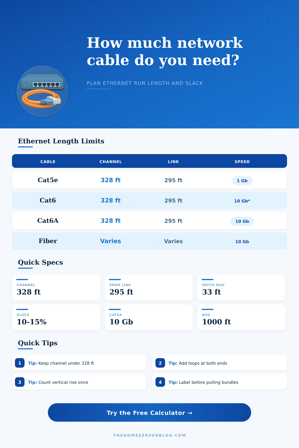
| Cable type | Channel limit | Permanent link | Home lab use |
|---|---|---|---|
| Cat5e UTP | 328 ft / 100 m | 295 ft / 90 m | 1 GbE drops, cameras, basic access points |
| Cat6 UTP | 328 ft / 100 m | 295 ft / 90 m | 1 GbE and short 10 GbE runs in quiet bundles |
| Cat6A UTP | 328 ft / 100 m | 295 ft / 90 m | 10 GbE to office, NAS, and lab benches |
| Cat6A shielded | 328 ft / 100 m | 295 ft / 90 m | 10 GbE near electrical noise when bonded correctly |
| OM3 or OM4 fiber | Depends on optic | Depends on optic | Rack uplinks, garage links, and electrical isolation |
| OS2 singlemode | Optic dependent | Optic dependent | Long backbone links with huge distance margin |
| Configuration | Typical runs | Slack pattern | Planning note |
|---|---|---|---|
| Single room drop | 1 to 2 | 4 to 8 ft each end | Measure path, not straight-line room distance. |
| Patch panel bundle | 6 to 24 | Extra rack dressing loop | Pull multiple labeled cables from one box carefully. |
| PoE camera run | 1 to 8 | Small device loop at eave | Keep outdoor jacket and drip loop in the plan. |
| Ceiling access point | 1 to 2 | Loop above ceiling tile | Leave enough slack for AP replacement. |
| Garage conduit | 1 to 4 | Pull box service loop | Use fiber when lightning or ground potential is a concern. |
| Rack uplink | 2 to 4 | Patch cord controlled | Channel limit may be driven by patch leads. |
| Route factor | Added allowance | Where it applies | Why it matters |
|---|---|---|---|
| Open basement | 2% route factor | Joists, tray, unfinished space | Few hidden detours and easy straight pulls. |
| Stud bay | 6% route factor | Wall cavities and plates | Small offsets and fishing path uncertainty. |
| Attic route | 8% route factor | Top plates, rafters, ceiling drops | Longer paths around obstructions. |
| Conduit pull | 10% route factor | Sweeps, pull boxes, underground | Pulling and termination usually need more waste. |
| Crawlspace | 9% route factor | Under-floor routes | Detours around HVAC, plumbing, and blocking. |
| Outdoor conduit | 12% route factor | Exterior or buried raceway | Weatherproof loops and transition points add length. |
| Project size | Equipment pattern | Common cable total | Secondary check |
|---|---|---|---|
| Home office drop | Router to one room, two jacks | 150 to 250 ft | Patch cords can consume channel headroom. |
| Small lab rack | Patch panel, switch, NAS bench | 250 to 500 ft | Leave rack slack for switch replacement. |
| Ceiling AP project | Two PoE APs from core switch | 180 to 350 ft | Check PoE voltage drop on long copper runs. |
| Camera bundle | Four to eight exterior cameras | 500 to 1000 ft | Plan drip loops and outdoor-rated cable. |
| Whole-house wiring | 8 to 16 structured drops | 900 to 1800 ft | Use multiple boxes to pull bundles evenly. |
| Garage backbone | Conduit link to remote switch | 150 to 400 ft | Fiber avoids copper surge paths. |
💡Planning tips
When calculating the length of a cable that will be installed into a network, it is important to calculate the actual length of the cable that will be installed. Many individuals will calculate the distance between two point on a map or a floor plan, but the actual length of the cable will be longer than the distance between those two points. The cable will have to travel through walls, floors, and joists.
Additionally, a network installer will have to purchase extra length in order to allow for adjustment in the location of network devices. Failure to account for the difference between the distance that is represented on a map or floor plan and the actual length of cable that will be installed will result in either installation costs that exceeds the budget for the installation job, or the network will underperform. The cable calculator will calculate the total length of the cable that will be required for a network based off the route that is to be used, the number of network runs that are to be performed, and the type of data cable that will be used.
How to Calculate Network Cable Length
The calculator will separate entries for the permanent in-wall data cable from the length of patch cords that will be used to connect to network devices. Allowances are made for the bends in the data cable, service loops in the route, and for the inclusion of a small buffer of extra network cable. The purpose of the calculator is not to provide a length of data cable that will be purchased by a network installer, but the purpose of the calculator is to allow the installer to see which element of the network use the most available headroom, and which elements has extra headroom within the network design.
The distance that is calculated for copper data cables must account for the limits of the copper data channel, which includes all of the segments of copper data cable between a switch port and a network device. The permanent link length of the data cable is the length between the switch and the device that is located within the walls, and the permanent link has its own limit for length. By calculating the length of the permanent link and the length of the data channel, a network installer can determine if a selected route will accommodate the network devices after the length of the patch cords is added to each end of the data channel.
Fiber optic cables behave different than copper data cables. Fiber optic cable has a large headroom for distance within the data channel. Fiber optic data cable still, however, requires allowances for bends in the cable, and fiber optic data cable will require service loops to allow for re-termination of that fiber optic data cable in the future.
Fiber optic entries and copper data cable entries are separated within the calculator so that the different standard for each type of data cable are maintained. When a user selects fiber optic data cable of a specific type for use in a network, the warnings that the calculator provides regarding distance will decrease, but the recommendations regarding slack and service loops will remain the same. The difficulty of the route of the data cable is an entry that is required by the calculator.
Data cable that runs through an open area of a basement is an easy route, but data cable that is to run through an attic that contains other installed cables, or that runs through exterior conduit is a difficult route. Each different route type has an additional length of data cable that is required for the route to allow for bends in the data cable, for pull boxes, and in the inability of the installer to pull the data cable in a perfectly straight line along its route. The percentage factor for each type of route is provided as a means of reminding installers that the route that appears on a floor plan is rarely traveled in the same manner in the actual building.
Service loops are areas that is often different between network installation plans and reality. A service loop is created at each end of a data cable to allow for the movement of network devices or keystone network jack boxes. A two foot length of service loop at each end of a data cable may appear to be a significant length of data cable, but without the service loop, the network will not be able to accommodate the movement of network devices.
The length of the service loop and the number of service loops can be entered into the calculator so that the total length of the service loop for an entire network can be viewed. The length of patch cords that are used in a network is another entry that is important to the calculation of the total length of data cable that will be purchased. The length of patch cords will reduce the length of the data channel for that network.
The reference tables that appear in the data cable calculator entry list some of the types of data cables that are available for installation in a network, and the types of networks for which those data cables are typically used. These tables can be used to determine which types of data cable are to be used in a network installation. For instance, Cat6A data cable is often used for new installations of copper data cable, as it provides headroom for data transfer rates of 10 GbE.
Shielded data cables provide protection from electromagnetic fields, which are created by power lines and other electrical devices. However, the shielded data cables must be properly bonded for the protection to be provided to the data cable. Additionally, the tables show the distance headroom that is provided by fiber optic data cable, which is useful for networks that connect buildings, or for networks that pass through areas of the earth that have different ground potentials.
Many individuals make mistakes when planning the installation of a network. For instance, the distance between the network switch and the device is sometimes measured to the nearest wall plate, rather than to the device itself. Many individuals dont account for the vertical distance between the switch and the device.
Additionally, many network installations plan for one long pull of data cable rather than for the data cable to be pulled into a network box. Finally, many individuals do not account for the length of data cable that will be lost when the cable is trimmed and re-terminated to provide an even installation. The value of the data cable calculator is that each variable in the network installation can be adjusted to see how that adjustment impacts the length of data cable that will be required.
Increasing the number of data cable runs will increase the total length of data cable. Increasing the length of the patch cords will reduce the length of the data channel. Changing the type of route that is used for the data cable will impact the length of the data cable needed to accommodate the changes in route difficulty.
A network installer can each adjust these variables using the data cable calculator to determine the number of data cables of each type that will be required to install the network. A good plan for installing a network will allow for the route of the data cable to have some length in excess of the distance that the data will must travel. The network should account for the distance limits of the cable type, the length of slack that is permitted for network devices, the number of service loops that are required for flexibility in the network, and ensure that the cable is not under tension when it is installed.
These allowances ensure that the network will be installed within the limits of the standards for that type of network. Once the individual becomes comfortable with the numbers that the calculator calculates, the installation of the data cable can proceed with confidence.