RF Cable Attenuation Calculator
Estimate coax feedline loss from cable type, frequency, run length, connectors, splitters, mismatch, weather allowance, and planning buffer.
Loss and link breakdown
Attenuation values are typical manufacturer-style planning numbers. Exact cable loss changes by manufacturer, temperature, jacket condition, connector quality, and installation workmanship.
| Cable type | Typical use | 150 MHz | 450 MHz | 900 MHz | 2.4 GHz |
|---|---|---|---|---|---|
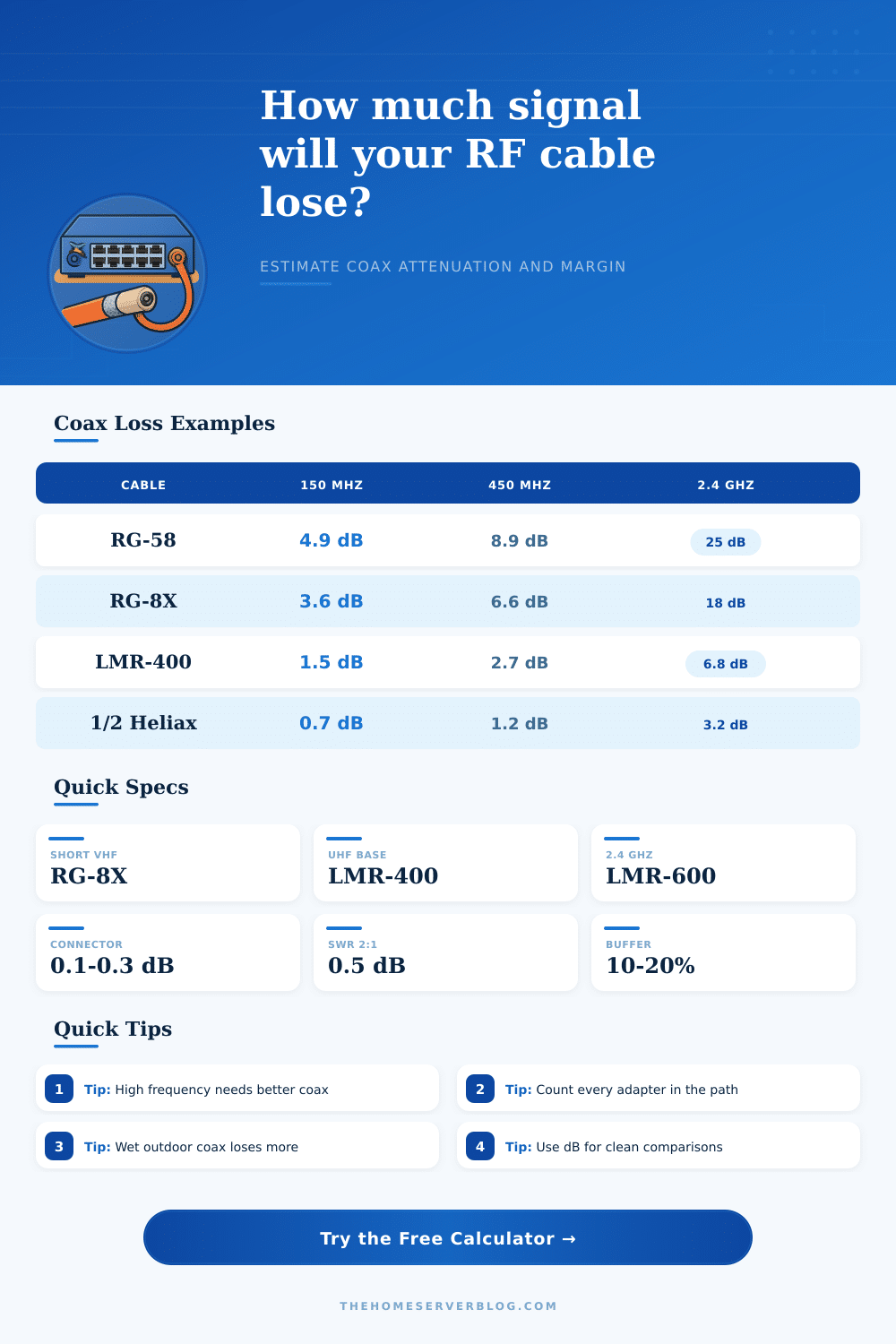
| RG-58/U | Short jumpers, low-cost VHF | 4.9 dB | 8.9 dB | 13.5 dB | 25.0 dB |
| RG-8X Mini-8 | Portable HF/VHF, moderate runs | 3.6 dB | 6.6 dB | 10.0 dB | 18.0 dB |
| RG-213/U | Rugged HF/VHF base stations | 2.7 dB | 5.0 dB | 7.6 dB | 13.8 dB |
| LMR-240 | Flexible low-loss small cable | 2.8 dB | 5.1 dB | 7.8 dB | 13.2 dB |
| LMR-400 | Common UHF and Wi-Fi mast runs | 1.5 dB | 2.7 dB | 3.9 dB | 6.8 dB |
| LMR-600 | Long UHF and microwave feedlines | 0.95 dB | 1.7 dB | 2.5 dB | 4.4 dB |
| RG-6 Quad Shield | TV, broadband, receive-only runs | 2.9 dB | 5.4 dB | 6.7 dB | 12.9 dB |
| 1/2 in Heliax | Low-loss repeater and tower lines | 0.68 dB | 1.2 dB | 1.8 dB | 3.2 dB |
| Item | Planning loss | Where it appears | Why it matters |
|---|---|---|---|
| Quality N connector | 0.05-0.15 dB | Outdoor VHF/UHF | Low loss and weatherable when installed well |
| PL-259 / SO-239 pair | 0.10-0.25 dB | HF and VHF ham gear | Fine at HF, less ideal as frequency rises |
| SMA or RP-SMA adapter | 0.10-0.30 dB | Wi-Fi, SDR, LoRa | Small adapters add up quickly in weak-signal paths |
| Two-way TV splitter | 3.5-4.0 dB | TV coax distribution | Often larger than the cable loss itself |
| Duplexer or cavity filter | 0.7-2.0 dB | Repeaters | Must be budgeted before judging antenna power |
| Lightning arrestor | 0.10-0.30 dB | Mast entry points | Small but real, especially with adapters |
| Project | Frequency range | Typical run | Loss target | Cable class |
|---|---|---|---|---|
| HF shack dipole | 3-30 MHz | 50-100 ft | Under 1 dB | RG-8X, RG-213, LMR-400 |
| VHF/UHF roof antenna | 144-450 MHz | 40-100 ft | Under 2-3 dB | LMR-240, LMR-400 |
| ADS-B receiver | 1090 MHz | 15-60 ft | Under 3 dB | LMR-240, LMR-400, preamp near antenna |
| 2.4 GHz bridge | 2400 MHz | 5-30 ft | Under 2 dB | LMR-400, LMR-600, short pigtails |
| 5.8 GHz bridge | 5800 MHz | 3-15 ft | Under 2 dB | Very short coax or radio at antenna |
| TV attic distribution | 50-700 MHz | 50-150 ft | Check splitter loss | RG-6 quad shield |
| Reference | Useful value | Calculator use | Planning note |
|---|---|---|---|
| Power ratio | 3 dB = half | Delivered watts | A 3 dB feedline loss leaves about 50% of transmitter power |
| Power ratio | 10 dB = tenth | Loss severity | A 10 dB loss leaves about 10% of transmitter power |
| Metric length | 1 m = 3.28084 ft | Unit toggle | Most coax attenuation sheets are listed per 100 ft |
| 50 ohm coax | Radio standard | RF systems | Common for ham, commercial radio, Wi-Fi, LoRa, SDR |
| 75 ohm coax | TV standard | Receive systems | Common for OTA TV and cable distribution |
| Outdoor derate | 5-25% | Allowance | Moisture, bends, age, and adapters raise practical loss |
Attenuation is the loss of a radio signal as a radio signal travels through an length of coaxial cable. As a radio signal travels through coaxial cable, some of the radio signal dissapears before it reaches the antenna. Because attenuation can reduce the range and the reliability of a radio link, attenuation is one of the most important factors to consider in the installation of a radio link.
Many radio link installations dont perform to there potential due to attenuation. The calculator on this page allow you to calculate the amount of attenuation that will occur before you purchase your coaxial cable. You must enter the type of coaxial cable that you plan to purchase, the operating frequency of your radio link, the length of the coaxial cable run, and the number of coaxial cable connector and adapters that you will use.
Coax Cable Signal Loss and How to Calculate It
Based off these entries, the calculator will provide three specific number to you: the total loss of the signal, the power of the signal that reaches the antenna, and the margin on the receive side of your radio link. These three numbers will allow you to determine whether or not the coaxial cable that you are considering will meet the requirements of your radio link; otherwise, youll know that you must purchase a different type of coaxial cable. Radio signal attenuation increase as the frequency of the radio signal increases.
For instance, RG-8X coaxial cable will lose a small amount of signal when the signal frequency is set to 150 MHz, but the same coaxial cable will lose much more signal when the frequency is set to 2.4 GHz. Because of this relationship between frequency and attenuation, many microwave radio links will position the radio transmitter on the mast of the antenna tower so that the radio signal does not have to travel through the coaxial cable for long distance. The engineer doesnt need to calculate this frequency dependence of attenuation using this calculator.
The length of the coaxial cable will impact the amount of attenuation of the radio signal. However, many engineers and designers of radio links do not account for all of the length that the coaxial cable will actualy need to travel to the antenna. The length of the coaxial cable may be longer than the distance that is measured on the building plan for the installation of the antenna.
Furthermore, the coaxial cable will need to travel around obstacles, creating more length for the signal to travel. If the length of the coaxial cable is underestimated, the link may not meet the design requirement for performance. Thus, the calculation of attenuation must account for the length of the coaxial cable.
The number of coaxial cable connector or adapters that are used will impact the attenuation of a radio link. Each N-type or SMA adapter will add to the loss of the signal. Thus, if you use three or four adapters in the installation of a radio link, the total attenuation will be more higher than if the signal travels through fewer adapters.
Other accessories that are placed into the radio link will also cause some loss of the signal strength. Each of these accessory can be accounted for in the coaxial calculator. The outdoor environment in which the coaxial cable is installed will impact the attenuation of the signal over time.
If the coaxial cable is exposed to moisture, changes in temperature, and sharp bends in the coaxial cable, the attenuation will increase over time. The environment-derate option allows for this change in attenuation to be accounted for in the coaxial cable attenuation calculator. While this option isnt an exact science in measuring the amount of attenuation that will occur due to the outdoor elements, the environment-derate option allows for the estimate of the attenuation of the signal to not be too optimistic about the performance of the coaxial cable over the years.
The outputs of the coaxial cable attenuation calculator will provide information regarding the performance of the radio link if you construct the radio link according to the parameters that are entered into the calculator. The delivered power will provide information as to how strong the signal is that reaches the antenna. The receive margin will provide information regarding how strong the signal is after it passes through the coaxial cable to the antenna, but before the radio link receiver receives it.
The receive margin will determine whether the link is vulnerable to signal issue. A large receive margin indicates that the signal will be able to perform good under seasonal changes. In choosing the type of coaxial cable that will be used in the installation of a radio link, there are tradeoffs that must be made.
Thicker coaxial cable will exhibit less attenuation than thinner coaxial cable. However, the thicker the coaxial cable, the more money that will be required to purchase that cable, and the more difficult that it will be to route that cable to the antenna. Thinner coaxial cable will be less expensive and easy to route, but the link will have a limited length and frequency that can travel the signal along that coaxial cable.
The coaxial cable attenuation calculator can be used to compare these scenario to determine the best type of coaxial cable for the link. The purpose of the calculator is to ensure that the attenuation of the signal is within the performance envelope that is established for the link.