HomeServerBlog cable pathway planner
Cable Tray Fill Capacity Calculator
Estimate usable tray cross-section, fill percentage, remaining cable count, support weight, lane allowance, bend radius clearance, and spare capacity before adding new home lab runs.
1Cable tray presets
2Tray, cable, and support inputs
Area and cable breakdown
Capacity health
3Area, fill, weight, and remaining cards
Total inside cross-section before fill-height, lane, or spare deductions.
Round cable cross-section multiplied by the installed cable count.
Estimated cable load carried between adjacent tray supports.
Similar cable count that fits after the spare-area reserve.
4Tray type comparison grid
5Cable tray capacity tables
Current tray fill breakdown
| Planning item | Value | Formula basis | Tray note |
|---|---|---|---|
| Gross area | 48 sq in | Width x depth | Inside tray dimensions. |
| Fill-height area | 21.6 sq in | Area x height percent | Depth limit before reserves. |
| Usable area | 16.6 sq in | Height area minus lane and spare | Design capacity for cable. |
| Cable area | 2.0 sq in | OD circle area x count | Installed bundle estimate. |
Cable OD capacity using current tray settings
| Cable outside diameter | Area each | Estimated max count | Best use |
|---|---|---|---|
| 0.18 in | 0.025 sq in | 650 | Thin fiber jumpers or small control cable. |
| 0.23 in | 0.042 sq in | 400 | Typical Cat6 home lab bundle. |
| 0.30 in | 0.071 sq in | 234 | Shielded data or heavier low-voltage cable. |
| 0.50 in | 0.196 sq in | 85 | Coax, power-limited cable, or mixed runs. |
Support span load check
| Support span | Cable load per support | Approx metric load | Planning note |
|---|---|---|---|
| 4 ft | 6.7 lb | 3.0 kg | Short span with lower deflection risk. |
| 5 ft | 8.4 lb | 3.8 kg | Current input support distance. |
| 8 ft | 13.4 lb | 6.1 kg | Verify tray rating and anchors. |
| 10 ft | 16.8 lb | 7.6 kg | Often needs stronger supports. |
Common tray planning reference
| Tray size | Gross area | Typical fill target | Home lab use case |
|---|---|---|---|
| 4 in x 2 in | 8 sq in | 30% to 40% | Small wall closet, AP drops, or short lab shelf. |
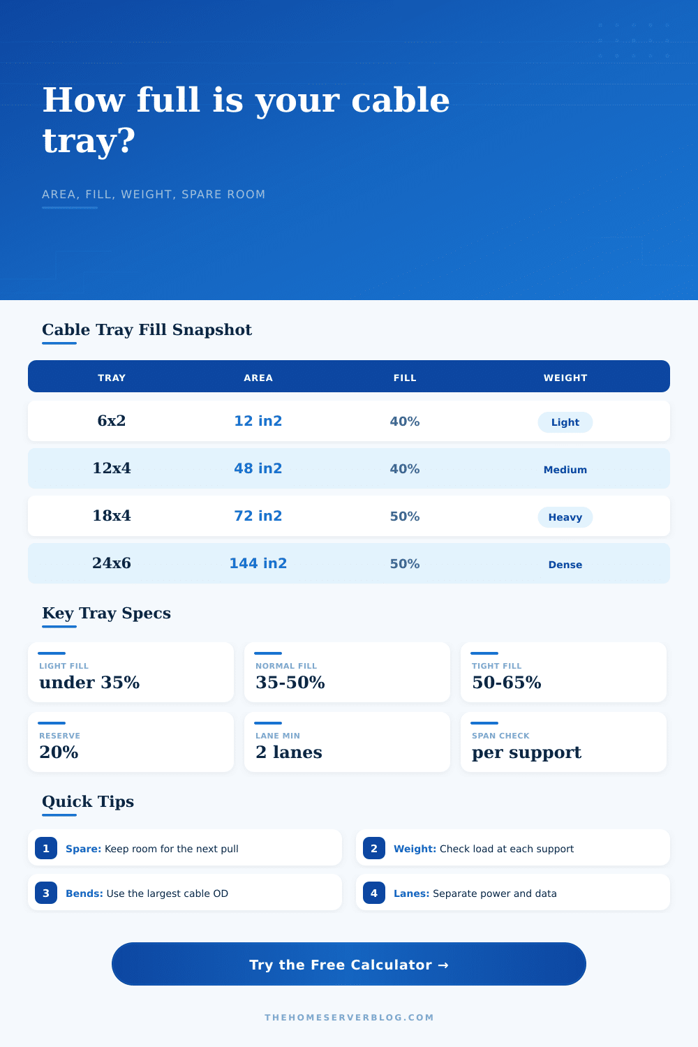
| 6 in x 2 in | 12 sq in | 35% to 45% | Starter rack bundle with room for future copper. |
| 12 in x 4 in | 48 sq in | 40% to 50% | Mixed patch, PoE, fiber, and NAS bench cabling. |
| 18 in x 4 in | 72 sq in | 40% to 50% | Rack row backbone or larger structured cabling path. |
| 24 in x 6 in | 144 sq in | 45% to 55% | Dense utility room or multi-rack home lab pathway. |
6Cable tray fill tips
This calculator is a planning aid for home lab and low-voltage pathway sizing. Confirm tray manufacturer ratings, electrical code, firestopping, grounding, separation, and local inspection requirements before installation.
Every home lab project eventually reaches a turning point where the plan encounters reality. You bought the switches, picked out the rack, even placed an order for some fiber optic cables. And then you remember about cable tray running over your server row. Is that big enough? It certainly seems like there’s some breathing room between bundles on the tray. But how can you tell from just looking at bundle of cables?
Turns out visual estimating isn’t very accurate. One tray could be structurally maxed out even though it looks half empty. Another has significant capacity remaining even though it look full. If you guess wrong, either you’ll put so many cables in a tray that it sags (bad) or you’ll run out of pathways before adding that new device someday (also bad).
How to Size Your Cable Tray
Limits is defined by both weight and volume. You don’t need to guess. You don’t need to know conversions and coefficients. Plug-in your cable specs and tray dimensions and let the calculator do the math.
It will also force you to calculate your fill height percentage. Meaning: How deep will your cables go? How much air flow/room do you want? What’s the practical maximum? You can have a large tray that has a big gross area. But what happens when you only fill that same tray 50% of the way deep? If you exceed the fill height percentage, it gets crushed or piles up. Your usable space decrease a lot. Most people overlook this portion. If they want to house every single thing they have, then they’ll purchase the largest tray available and hope it fits. They ignore the fact that cables stack and that the laws of physics are at play.
Weight is equally quiet. Even with lots of room on a given cross section, you may be overloading the supports. Thick shielded data lines and power-limited fire safety cables really start to accumulate there. The tool also breaks down the load on each support span. Why does that matter? Every hanger point needs to handle its share of weight which depends on the distance between them.
In most residential installations, it’s five foot; but when you stretch that to eight or ten feet (without intervening supports), you’re likely to see bowing in tray itself. And if the tray bows, the cables will either strain their connection points or shift position…perhaps even falling out entirely if the side rails is too low. This is structural failure dressed up as a cabling issue.
One more variable that tends to get treated as an optional decor item are separation lanes. If you’re running coax, fiber, data, and high-voltage power in the same tray, they should be physically separated. Not only does this make troubleshooting simpler but it also helps prevent interference. By assigning lanes with the calculator, you can essentially count the dividers and empty space between your groups when reducing the available area. It is a small thing, but it matters.
Why keep power and data separate? Because it’s not just about following code, it’s about sanity. You don’t want to have to dig around and disturb a bundle of heavy power cables when all you need is one Cat6 cable. Enter the lane input to reserve that breathing room at the design stage. This way, you won’t find out the space isn’t there after the tray has been sealed.
The last limitation is one designed to preserve the cable itself: Bend Radius. Each cable has a minimum bend radius (usually expressed as a multiple of its outside diameter). When forcing a cable to bend smaller than it’s comfortabley with, you have a high probability of damaging either the insulation or the conductors within the wire. These problems show up intermittently. Very difficult to troubleshoot.
To prevent these costly mistakes, the calculator takes into account this multiplier so that the routes you plan will physically fit through any turns in the path. An easy check provides easy peace of mind.
Planning cable trays is an exercise in prediction. How far into the future do you plan? Do you have sufficient space for expansion without buying too big? What is the right mix of separation, weight, and area to ensure it’s serviceable while still being strong? It’s always preferable to leave 20% of tray vacant rather than needing to re-drill the drop ceiling when growth occurs. The cables need to fit now; but they should of fit easily the next time.
Build a lab that feels easy to update. That’s what makes a lab last.