Cable Velocity Factor Calculator
Estimate cable propagation delay, infer measured velocity factor, convert frequency to cable wavelength, and check electrical length for coax, twisted-pair Ethernet, and fiber patch runs.
Cable velocity factor result
| Cable family | Typical VF or NVP | Delay reference | Planning note |
|---|---|---|---|
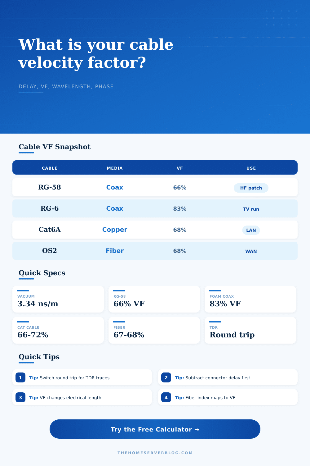
| Solid PE coax | 0.66 | About 1.54 ns/ft or 5.05 ns/m | Common for RG-58 and older solid-dielectric cables. |
| Foam coax | 0.78 to 0.88 | About 1.15 to 1.28 ns/ft | Higher VF shortens electrical length for the same physical run. |
| Twisted pair | 0.64 to 0.72 NVP | Often near 4.8 to 5.2 ns/m | Pair-to-pair skew matters for precise Ethernet timing. |
| Glass fiber | 0.67 to 0.68 | Near 4.9 to 5.0 ns/m | Equivalent VF is 1 divided by refractive index. |
| Measurement item | Formula used | Best input | Common mistake |
|---|---|---|---|
| One-way delay | Length / (c x VF) | Known cable length and datasheet VF | Forgetting to convert round-trip TDR time to one way. |
| Measured VF | Length / (c x one-way delay) | TDR or pulse delay with fixture delay removed | Leaving adapter and launch delay in a short cable test. |
| TDR trace delay | 2 x one-way delay + connector delay | Round-trip mode for reflectometer traces | Comparing TDR delay directly to one-way datasheets. |
| Temperature correction | VF x (1 + correction percent) | Known lab or field correction factor | Treating all cable families as having the same drift. |
| RF length target | Electrical phase | Physical length in cable | When it matters |
|---|---|---|---|
| Quarter wave | 90° | Cable wavelength / 4 | Stubs, matching sections, and phasing harnesses. |
| Half wave | 180° | Cable wavelength / 2 | Repeating impedance at the far end of a feed line. |
| Full wave | 360° | One complete cable wavelength | Comparing phase wrap and resonance at a frequency. |
| Timing match | Delay based | Extra length = c x VF x delay | Matching receive chains, trigger paths, or lab fixtures. |
| Network cable type | Standards context | Delay clue | Calculator use |
|---|---|---|---|
| Cat5e / Cat6 | 100 m channel limit for twisted-pair Ethernet | Nominal velocity propagation is usually listed as NVP. | Estimate tester length and one-way latency for LAN segments. |
| Cat6A / Cat8 | Higher bandwidth balanced copper links | Pair skew can be more important than average VF. | Compare patch and permanent-link timing in racks. |
| OM3 / OM4 fiber | Multimode data-center fiber | Index near 1.49 gives VF near 0.67. | Estimate propagation delay between switch ports. |
| OS2 fiber | Singlemode campus, metro, and WAN fiber | Index near 1.468 gives VF near 0.681. | Convert route length to latency budget for long links. |
It’s possible to create a feed line with the right length, but still have it perform badley. How? Because inside the feedline wire, radio waves don’t travel at speed of light. That’s what this calculator does for you. When you input the frequency and type of cable, it crunches numbers. You won’t have to guess about converting units or messing around with coefficients. It gives practical, real world inches and nanoseconds out of complex physics.
One other point: Velocity factor is a term which refer to the rate of travel of a wave within a given medium as a fraction of velocity of light in a vacuum. In free space, light travels at approximately three hundred million meters per second. Within a coaxial cable, using solid polyethylene insulation, that figure is reduced to approximately sixty-six percent of free space. For foam dielectric cables, the number climbs back up and often exceeds eighty percent. Because fiber optic cables operates according to the refraction properties of their glass core, there is another rule at work here. These figures are all included in the reference table found on the page.
Why Physical Length Is Not Enough
From this table you will see the number of feet or meters of delay you will experience for any given type of cable. This matters since a ten foot jumper physically appears identical whether it has foam insulation or solid insulation. Electrically though, it could differ by several feet of electrical phase shift.
A common error I see is when folks take distance from the outside edge of one connector to the next on an assembly. This provides physical length, not the electrical length. In order to get anything useful with these calculations, you must have the one way propagation delay.
Faults can easily be located with TDR tools in Time Domain Reflectometry. However, the TDR is a round trip measurement. So the signal travels down the wire, strikes the far end and bounces back up the wire. Unless you divide this raw number from the tool by 2, you’ll calculate a velocity factor that is twice as large than it actualy is. The TDR does this automatically by providing switches to select between one way and round trip measurements. It is a small user input but it is significant nonetheless.
Another part of this calculation that is frequently overlooked are subtracting out connector delay. Launch fixtures and adapters all have their own little amount of delay (a few nanoseconds). When added to a short patch cord, the additional nanoseconds can throw off your computed velocity factor by several percentage points.
If you’re designing matching stubs or phasing arrays, wavelength is now your limiting factor. In free space, the wavelength is determined by the frequency of your signal. However, because we are using cable, you must take the cable’s velocity factor into account. This factor will compress the wavelength. For example, a quarter-wave stub for a one-hundred forty-six megahertz signal would be six feet long in free space but only four feet within a fifty-ohm RG-58 cable.
If your impedance matching network isn’t correct in phase, it won’t send the energy from your transmitter into the antenna. Instead it’ll reflect the power back where it came from. On paper, the numbers may appear correct, but the VSWR meter speaks the truth. The calculator takes your frequency and type of cable and translates that into real world wavelength inside the wire, allowing you to cut your cable down to exactly the electrical length required.
Even subtle factors such as temperature have an impact on high precision applications. The dielectric constant of plastic changes slightly with heat. That may be negligible in casual use but could lead to performance problems over time in a lab environment or out in the field. One percent change in velocity factor is barely noticeable by the casual user. It’s guaranteed to be noticed by engineers who build precise timing links and phased arrays. If you’re operating at tight tolerances, there is a small temperature correction factor provided in the tool.
Cable is not just a passive conduit for electrons; it is a resonant structure that interacts with the signals it carries. Cable is a resonant structure that also reacts to what passes through it. Velocity factor links the electrical world of wavelengths and phases with physical world of spools and tape measures. From tuning HF amateur stations to running Ethernet cabling in data centers, the delay in the cable matters if you want your system to work as intended.
It’s not about how fast you want the signal to go. It goes as fast as it wants. Knowing that difference makes the difference between guessing and designing. You should of used this tool sooner.