Modulation Bits Per Symbol Calculator
Estimate raw bits per symbol, coded payload rate, occupied bandwidth, spectral efficiency, and BER-driven SNR requirement from modulation order, coding rate, symbol rate, roll-off, streams, and overhead.
| Constellation | Formula | Raw bits/symbol | Typical use |
|---|---|---|---|
| BPSK / 2-FSK | log2(2) | 1 | Robust telemetry, low-rate control, weak-signal links. |
| QPSK / 4-QAM | log2(4) | 2 | Cellular control channels, satellite links, Wi-Fi low MCS. |
| 8-PSK / 8-FSK | log2(8) | 3 | DVB-style links and moderate SNR radio paths. |
| 16-QAM / 16-APSK | log2(16) | 4 | Balanced rate and robustness for microwave or cable paths. |
| 64-QAM | log2(64) | 6 | Common Wi-Fi, DOCSIS, OFDM, and fixed wireless mode. |
| 256-QAM | log2(256) | 8 | Clean WLAN, cable modem, and short microwave links. |
| 1024-QAM | log2(1024) | 10 | High SNR Wi-Fi 6, lab RF, and modern broadband PHYs. |
| 4096-QAM | log2(4096) | 12 | Very clean Wi-Fi 7, cable, or short-range links. |
| Coding rate | Payload share | Example on 64-QAM | Planning note |
|---|---|---|---|
| 1/3 | 33.3% | 2.00 coded bits/symbol | Strong protection when sensitivity matters more than throughput. |
| 1/2 | 50.0% | 3.00 coded bits/symbol | Common robust FEC for low SNR or mobile channels. |
| 2/3 | 66.7% | 4.00 coded bits/symbol | Middle ground for changing RF conditions. |
| 3/4 | 75.0% | 4.50 coded bits/symbol | Often used when the link has useful margin. |
| 5/6 | 83.3% | 5.00 coded bits/symbol | High throughput when the received constellation is clean. |
| 9/10 | 90.0% | 5.40 coded bits/symbol | Light protection for controlled or high-SNR paths. |
| Modulation | Bits/symbol | Approx SNR for BER 1e-5 | What changes it |
|---|---|---|---|
| BPSK or QPSK | 1 to 2 | 9 to 12 dB | Receiver implementation, coding gain, and interference. |
| 8-PSK / 16-QAM | 3 to 4 | 14 to 18 dB | Phase noise, linearity, FEC, and channel estimation. |
| 64-QAM | 6 | 22 to 25 dB | EVM, multipath, adjacent channels, and equalizer quality. |
| 256-QAM | 8 | 28 to 31 dB | Clean spectrum and low distortion are important. |
| 1024-QAM | 10 | 34 to 37 dB | High-end radios need close range and excellent EVM. |
| 4096-QAM | 12 | 40 dB or more | Very high SNR, low phase noise, and stable channels. |
| Family | Strength | Tradeoff | Common examples |
|---|---|---|---|
| PSK | Good power efficiency | Phase noise affects higher orders | BPSK, QPSK, 8-PSK satellite and control links. |
| QAM | High spectral efficiency | Needs linear RF and high SNR | Wi-Fi, DOCSIS, DSL, OFDM subcarriers, microwave. |
| APSK | Amplifier-friendly rings | Receiver complexity | DVB-S2/S2X and satellite MODCOD planning. |
| FSK | Simple robust receiver | Can need wider spacing | IoT radios, paging, metering, and low-rate telemetry. |
| PAM | Simple single-axis signaling | Amplitude noise sensitive | Ethernet PHYs, short electrical channels, optical links. |
| OFDM | Handles multipath well | Pilots, cyclic prefix, and PAPR overhead | Wi-Fi, LTE, 5G NR, DVB-T, and broadband links. |
The answer tends to be: change density; pack more information into every burst of energy. Except there’s no more room for this in your radio wave; you’re trying to force-feed more data through a pipe different than there’s any space for. You won’t understand until you see the math, and then it is just a matter of speed and fragility tradeoffs. It’s magic until you look at it.
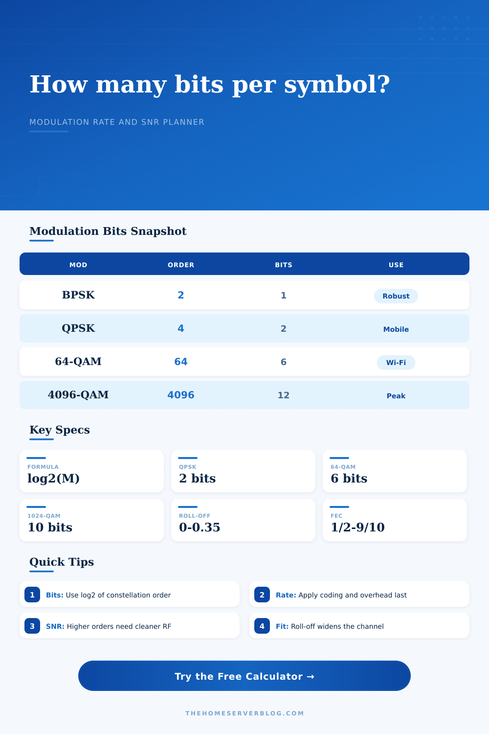
The tradeoff boils down to how many bits per symbol you are prepared to send. Binary Phase Shift Keying (BPSK) sends one bit per symbol, it’s extremely robust because all that the receiver needs to do is decide whether they’ve received a zero or a one. But it’s also slow. Go up to Quadrature Amplitude Modulation (QAM), which starts modulating not just the phase but also the amplitude of the carrier wave. Suddenly you’re able to map more than one bit into each symbol. For example, sixty-four-QAM sends six bits per symbol, while one thousand twenty-eight-QAM sends ten.
The Balance of Speed and Safety
Plug your constellation order into the calculator above and it will handle the math for you; you can worry about what those decisions mean in practice. Now, the issue with higher order modulation is you’re cramming those symbols in there on the constellation diagram until the symbols are right next to each other. The dots gets close enough that random noise bumps them over onto the next symbol. The receiver see this and makes a mistake.
You can’t simply increase your modulation order unless you know that the link is clean enough for it. Higher orders demand lower phase noise, better linearity in your amplifiers, and a cleaner RF environment in general. If you have a muddy channel, high-order QAM result in a very high bit error rate that no amount of retry logic should of completely make up for.
That’s where forward error correction comes into play. It is your safety net, allowing you to push harder. How do you add parity bits as overhead? Through coding rates. And a coding rate of one-half indicates that half the bits you’re transmitting are check sums. That allows the receiver some ability to fight through those errors stemming from the cramped constellation points; but it reduces your effective payload rate by half.
It’s an exercise in balancing efficiency (the overhead) with robustness (the code). The page’s reference table show this clearly. A strong code like one-third can protect a fragile high-order modulation, but it reduces total speed.
The other hard constraint is bandwidth. You may have enough SNR for four thousand ninety-six-QAM. However, you might not have enough spectrum width to carry that many symbols per second (your required symbol rate) at your desired data rate. The roll-off factor determines how wide a swath of spectrum the signal occupies. Ideally, this would be zero to make the signal theoretically efficient. However, this is unachievable in practice because transition bands would be too sharp.
In real life, we have to use some excess bandwidth on the filter to avoid adjacent channel interference and shape the signal, typicaly from zero up to zero point three five. That means more occupied bandwidth and lower spectral efficiency. This does not even include overhead like preamble, framing, and pilot tones, which all consume more of your payload.
The first thing to do when you plan a link is to determine the noise. Estimate or measure what SNR you’re capable of maintaining, not the maximum, and work backwards: how high a modulation order can you use and still have an error rate within acceptable limits? Now add some coding margin. Then look at the resulting symbol rate. See whether it is small enough to fit into the channel bandwidth when you consider the filter rolloff.
It’s a balancing act. Make the modulation too aggressive and it falls over in the face of noise. Too conservative and you’ll be leaving precious capacity unused on the table. You want to stay right on the edge of instability, squeezing out as much data per symbol as possible without the connection fail.