HomeServerBlog hydronic cooling planner
Chilled Water Flow Calculator
Estimate chilled-water GPM and LPM from cooling load, supply and return temperature, fluid type, glycol percentage, pipe length, pump efficiency, redundancy, and design margin.
▦Chilled-water presets
⚙Cooling load and loop inputs
Flow breakdown
Pump and loop check
▣GPM, LPM, delta-T, and tons cards
🔄Cooling loop comparison grid
Direct coil
Lowest parts count and easiest to balance when the chiller loop can serve the coil directly.
0 GPMBuffer tank loop
Adds thermal mass for short-cycling control and lets small loads behave more steadily.
0 GPMPlate exchanger
Separates fluids, pressure zones, or outdoor glycol but usually adds approach temperature.
0 GPMIn-row loop
Best for dense rack rows where chilled water stays close to the heat source.
0 GPM📋Hydronic chilled-water tables
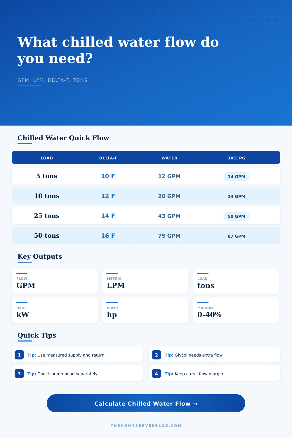
| Cooling load | 10°F water | 12°F water | 16°F water |
|---|---|---|---|
| 3 tons / 10.6 kW | 7.2 GPM | 6.0 GPM | 4.5 GPM |
| 5 tons / 17.6 kW | 12.0 GPM | 10.0 GPM | 7.5 GPM |
| 10 tons / 35.2 kW | 24.0 GPM | 20.0 GPM | 15.0 GPM |
| 25 tons / 87.9 kW | 60.0 GPM | 50.0 GPM | 37.5 GPM |
| 50 tons / 175.8 kW | 120.0 GPM | 100.0 GPM | 75.0 GPM |
Water table uses the common 500 constant before glycol, redundancy, and margin factors.
| Fluid mix | Heat factor | Flow impact | Use case |
|---|---|---|---|
| Water | 1.00 | Baseline | Indoor loops above freezing |
| 20% propylene glycol | 0.91 | About 10% more | Light freeze protection |
| 30% propylene glycol | 0.84 | About 19% more | Outdoor chilled-water piping |
| 40% propylene glycol | 0.77 | About 30% more | Colder freeze exposure |
| 30% ethylene glycol | 0.87 | About 15% more | Closed mechanical rooms |
Actual glycol properties vary by manufacturer and temperature; this calculator is a planning model.
| Pipe ID | Good GPM range | Watch range | Velocity note |
|---|---|---|---|
| 3/4 in | 2 to 6 | 7 to 10 | Small fan coils and short runs |
| 1 in | 4 to 12 | 13 to 18 | Compact lab loops |
| 1-1/4 in | 8 to 22 | 23 to 32 | Small chiller branches |
| 1-1/2 in | 12 to 35 | 36 to 52 | Rack coil headers |
| 2 in | 25 to 70 | 71 to 105 | Room loop mains |
Velocity guidance is approximate. Confirm noise, erosion, pressure drop, and control-valve authority separately.
| Loop type | Typical delta-T | Redundancy | Practical check |
|---|---|---|---|
| Fan-coil closet | 8°F to 12°F | 10% | Condensate and coil approach |
| Rear-door exchanger | 10°F to 16°F | 10% to 20% | Rack exhaust temperature |
| In-row cooler | 12°F to 18°F | 20% | Valve authority and bypass |
| Plate heat exchanger | 8°F to 14°F | 20% | Approach temperature |
| Economizer loop | 10°F to 18°F | 20% to 35% | Winter glycol and fouling |
If the measured return temperature is lower than expected, the loop may have excess flow or bypassed cooling water.
💡Two chilled-water sizing tips
A quick look through electrical load sheets and mechanical drawings shows a recurring issue with data center projects. Your assumed flow rate might not be enough for the cooling system to keep up with all of the servers pulling power. That chiller looks fine on paper, but water just won’t move the heat fast enough. This is where proper sizing come into play.
It’s not as simple as picking out a pump. You must know how all of those factors, volume, temperature, fluid properties, etc., work together to reach stability. Once you enter in your load and temperature spread, calculator does the math for you. You do not need to convert and estimate coefficients. Just save yourself the time.
Why Getting the Flow Rate Right Matters
So what is the heart of this issue? It is called the delta-T in engineering terms. That stands for the temperature change from where the water enters the coil compared to when it return back to the chiller. The bigger that differential, the more you can move same quantity of heat with smaller volumes of water.
If your swing is small like two degrees, then it takes massive pumps and large diameter pipe to push all that water around. If you open up that swing to say twelve or sixteen degrees, then you can shrink down the size of your pipes. Your pump will use less power. And your install becomes cheaper.
So this is a balance between lowering temperature rise (delta-T) but increasing the quantity of water moving through the system (flow). Most engineers design systems that has a ten to fifteen degree delta-T which makes a good compromise on control stability versus equipment costs.
Fluid type does affect performance as well. In general pure water transfer heat best due to its high specific heat capacity. That means it will absorb lots of energy without significantly increasing in temperature. Of course, since pure water freezes, you’d want to use a glycol solution when running pipes in unheated environments or outdoors. Ethylene glycol is toxic but stronger; propylene glycol is safe inside an enclosure.
Mixing in glycol alters the physics of the system. Each gallon can hold less heat, so a given amount of coolant need more volume to carry same cooling capacity. Depending on your mix, you might have to pump almost twenty percent more liquid to cool with a thirty percent propylene mix. This density adjustment is accounted for in the calculator, but be aware that higher viscosity adds both velocity cost and friction.
So how does it all fit together? Theory meets reality with pump selection. You can calculate the optimal flow. However, you then have to deal with head loss from valves, elbows, strainers, and long pipe runs. Each additional fitting add head loss.
The calculator will estimate what power is required depending off your entered head, but in reality, actual systems may create more friction than anticipated. Strainer clogs restrict flow and throw off that temperature difference. These failures are where redundancy helps. Oversizing your primary pump just a bit or adding a standby isn’t wasteful; it’s an insurance policy against oversight during maintenance.
What is margin? Margin in design gets confused. A fifteen or twenty percent margin isn’t meant to be a way of playing it safe. Instead, it recognize that the world will change, valves stick, coils get dirty, and new racks add mechanical load without updates. When conditions shift by a little bit your system fails because it was sized to the bare minimum. Having some extra space mean the system can run well. It enables the chiller to do its job well while the load fluctuates during the day.
Lastly, there’s velocity. If the water flows too slowly, dirt will settle out. Water also won’t flow well when it’s too slow. Bacteria will form in the dead spots. Too fast, water will create noise and begin to wear away at the pipes. Every diameter of pipe have an acceptable velocity range. Gentle flows are best for small lines. Higher velocities is possible with larger mains. See the chart on the page. This is the reference table for typical pipe sizes. Use this to make sure your calculated GPM matches what you have installed.
Balance is key with chilled water. Too little and it can’t get rid of the heat, too much and you’re wasting energy pumping water around. A too-wide temperature range makes controls unstable, too narrow and your equipment gets big. Proper flow rate help keep equipment steady, slows fans down, and lessens the work required by the chiller.
These small details matter when it comes to keeping systems running right. You should of checked everything twice. We naturaly want things to be perfect, but errors dissapear only with careful planning. It is actualy quite moddern how much we rely on these tools.