HomeServerBlog rack cooling planner
Rack Airflow CFM Calculator
Estimate server rack airflow from IT watts, target delta-T, rack count, server fan capacity, bypass air, altitude derate, redundancy, perforated tile output, containment type, and cooling margin.
Calculation breakdown
Airflow verdict
Open rack row
Fast to build, but mixing and short cycling usually require extra CFM.
1.25x CFMCold aisle containment
Best when intakes need stable temperature and raised floor tiles line the aisle.
0.95x CFMHot aisle containment
Captures return air well and helps chillers see a warmer, more useful return.
0.90x CFMDucted return rack
Works well for a single dense rack when exhaust has a clear path out.
0.86x CFM| Rack heat load | Watts | CFM at 15 F delta-T | CFM at 20 F delta-T | CFM at 25 F delta-T |
|---|---|---|---|---|
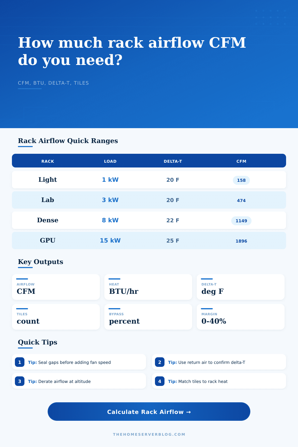
| Light network and NAS rack | 1,000 W | 211 CFM | 158 CFM | 126 CFM |
| Small virtualization rack | 3,000 W | 632 CFM | 474 CFM | 379 CFM |
| Busy home lab rack | 5,000 W | 1,053 CFM | 790 CFM | 632 CFM |
| Dense compute rack | 8,000 W | 1,685 CFM | 1,264 CFM | 1,011 CFM |
| GPU or storage-heavy rack | 15,000 W | 3,160 CFM | 2,370 CFM | 1,896 CFM |
Table values are base thermal CFM before bypass, containment leakage, altitude, redundancy, or margin adjustments.
| Containment type | Model factor | Common bypass range | Best use | Watch point |
|---|---|---|---|---|
| Open room, mixed aisles | 1.25x | 20% to 45% | Low density racks and temporary labs | Hot air can curl around rack sides. |
| Partial blanking and panels | 1.10x | 10% to 25% | Most home server closets and small rack rows | Unused U spaces need blanking panels. |
| Cold aisle containment | 0.95x | 5% to 15% | Several racks facing a shared cold aisle | Door leakage and tile placement matter. |
| Hot aisle containment | 0.90x | 4% to 12% | Higher density rack rows with return control | Return fans must keep heat from spilling. |
| Ducted return or chimney rack | 0.86x | 3% to 10% | One dense rack under ducted exhaust | Back pressure can reduce server fan flow. |
| Sealed in-row or rear-door path | 0.82x | 2% to 8% | Dense compute and known airflow paths | Monitor pump or fan redundancy closely. |
| Delivery path | Typical usable CFM | Good rack range | Layout note | Risk |
|---|---|---|---|---|
| 25% perforated tile | 200 to 450 CFM | 1 to 3 kW | Use multiple tiles for wider rack faces. | Low static pressure limits delivery. |
| 56% high-flow tile | 500 to 900 CFM | 3 to 7 kW | Place at rack intake line, not behind rack. | Too many tiles can starve other aisles. |
| Directional floor grille | 350 to 750 CFM | 2 to 6 kW | Aim discharge toward lower server intakes. | Jets can overshoot short racks. |
| Ducted rack base | 700 to 1,500 CFM | 5 to 12 kW | Balance pressure so all U positions receive air. | Obstructions create uneven inlet temps. |
| In-row or fan wall path | 1,500+ CFM | 10 kW and up | Coordinate fan speed with rack inlet sensors. | Redundancy planning becomes critical. |
| Observed symptom | Likely airflow cause | Calculator input to revisit | Measurement to confirm | Practical correction |
|---|---|---|---|---|
| Front intakes vary by more than 5 F | Uneven cold air distribution | Tile CFM and layout | Top, middle, bottom rack intake probes | Move supply closer to the starved intake area. |
| Server fans ramp at low CPU load | Recirculated hot air or blocked intakes | Bypass factor and containment | Fan PWM, inlet temperature, rack blanks | Add blanking panels and seal side gaps. |
| Return air stays only slightly warm | Too much bypass cooling air | Delta-T target and bypass | Supply and return temperature rise | Reduce excess tile flow and improve separation. |
| Rack overheats after one fan fails | No real redundancy margin | Redundancy factor and margin | Failure-mode airflow test | Reserve N+1 airflow or lower rack load. |
| High rack runs hot at altitude | Lower air density reduces heat pickup | Altitude derate | Site elevation and rack inlet trend | Derate CFM and raise fan or tile capacity. |
Start small: A closet rack might host a couple of virtual machines and maybe some storage. Everything looks good until fans start screaming. Chances are it’s not a fan failure… It’s a thermal one.
The cooling equipment can’t keep up with rejecting heat anymore because the air passing through it have lost its ability to do what it was intended to do. Airflow isn’t just about volume; it is about delivering cool air to intake and removing hot air from the exhaust without letting the two streams mix.
How to Keep Your Servers Cool and Quiet
Once you grasp this dynamic, the mathematical aspect of determining the right size for your cooling become more tangible and not so hard to understand. This all boils down to a basic fact of thermal dynamics: Every watt your IT gear consumes becomes heat within its enclosure… Be that a lightweight network switch or a tight cluster of GPUs. That’s going to have to go somewhere.
There’s an equation within the data center industry that link this heat load to the necessary airflow. It considers how hot the air exiting the rack should be relative to the air entering, which is known as the delta-T (temperature difference) through hardware. The more temperature difference you accept, the smaller volume of air you’ll require to transport that heat out.
It’s a tradeoff. Accepting a higher airflow will let you keep exhaust temps moderate, while requiring larger air supply paths and consuming more fan power. Alternatively, you can increase the delta-T. This makes it easier by requiring less airflow but it moves more heat out of the exhaust air.
The calculator above will compute this for you once you enter target temps and loads. There is no need for guessing, converting, or figuring out coefficients.
Bypass air is underestimated by most people. Bypass air is either the hot air that recycles back into the intake, or the cold air coming out the other side of the rack that never gets passed through any server. If your racks are in an open room with mixed aisles, it’s easy to have over thirty percent bypass, which isn’t much until you think about cooling empty space instead of your chips.
Sometimes sealing the rack up works better than increasing airflow. You can reduce bypass by using side panels to control the flow and blanking panels on unused U-spaces. You should of also control cables so they don’t obstruct vents. The goal is forcing the air past the equipment, not around it.
And then there’s altitude. Many admins is surprised by how much it plays into things. As you get higher up, the air gets thinner and has less density; that is, less thermal mass per cubic foot of air. If you size your system for sea level but put it somewhere at high altitude, it’s going to have problems. Thinner air require more volume to displace the same amount of heat.
Enter a derate percentage into the tool to account for lack of density. This ensures your plan works wherever your rack is located, not just where manual was written.
The last link in the chain is floor tiles for raised-floor data centers. Every tile can deliver only as much usable airflow. Exceeding its capacity result in reduced static pressure within the plenum, causing the tile to fail to deliver air effectively. Where the tiles sit in relation to the rack intakes matter, too; a tile located behind a rack will cool it … zero.
Use the reference tables to ensure your tile output match your rack load, enough delivery without wasteful over-delivery along unused paths.
The bottom line: It’s all about balancing containment, volume and pressure. It must be the right amount, flowing through the right path, at the right temperature. That balance results in keeping the noise down, extending the life of your hardware and preventing any hot spots.
Your system runs cool and the fans are quiet when airflow has been designed correcty. No more chasing temperature alarms, it’s time to focus on what those servers was built for.