HomeServerBlog RF cable planner
Coax Cutoff Frequency Calculator
Estimate the first higher-order coax mode from conductor geometry, dielectric constant, selected mode family, cable class, connector launch quality, safety margin, operating frequency, and run loss.
1Coax presets
2Geometry, dielectric, and operating inputs
Calculation breakdown
Mode status
3Coax comparison grid
4Geometry summary cards
Outer shield inner diameter divided by inner conductor diameter.
Average dielectric thickness between conductor surfaces.
Approximate ideal coax impedance from geometry and dielectric constant.
Used for wavelength and electrical length outputs.
5Coax geometry reference tables
| Geometry rule | Formula used | What it means | Planning note |
|---|---|---|---|
| TE11 cutoff estimate | c / (pi(a + b)sqrt(er)) | Lowest common higher-order coax mode | Keep operating frequency comfortably below this value. |
| TM01 radial estimate | c / (2(b - a)sqrt(er)) | Mode tied to dielectric gap thickness | Small gaps push this estimate higher. |
| Diameter ratio | D / d | Outer shield inner diameter over inner conductor diameter | Also drives characteristic impedance. |
| Coax impedance estimate | 138 log10(D / d) / sqrt(er) | Ideal round coax TEM impedance | Real cable dimensions and foaming can shift the value. |
| Cable family | Inner conductor | Shield ID estimate | Typical use |
|---|---|---|---|
| RG-58 / RG-174 class | Small stranded or solid copper | 2 to 3 mm | Short RF jumpers, HT adapters, lab leads. |
| RG-6 / RG-59 75 ohm | Copper-clad steel or solid copper | 3.7 to 4.8 mm | TV, satellite, CCTV, SDR receive feeds. |
| RG-213 / LMR-400 size | Large copper or copper-clad aluminum | 7 to 8 mm | HF, VHF, UHF, Wi-Fi bridge, base station runs. |
| Semi-rigid and hardline | Precision solid center conductor | 2.9 mm to 12 mm | Microwave paths where connector quality matters. |
| Dielectric | Approx er | Velocity factor | Effect on cutoff |
|---|---|---|---|
| Air spaced | 1.00 to 1.10 | 0.95 to 1.00 | Highest cutoff and longest wavelength. |
| Foam polyethylene | 1.35 to 1.65 | 0.78 to 0.86 | Common low-loss cable compromise. |
| Solid polyethylene | 2.25 | 0.66 | Lower cutoff than foam for the same geometry. |
| PTFE | 2.05 to 2.20 | 0.69 to 0.70 | Stable, heat-tolerant microwave dielectric. |
| Connector class | Launch derate | Loss allowance | Practical note |
|---|---|---|---|
| Precision 3.5 mm / quality SMA | 2 percent | 0.06 dB each | Best for microwave bench paths and calibration kits. |
| N type outdoor RF | 4 percent | 0.08 dB each | Strong choice for VHF, UHF, and low microwave outdoor runs. |
| BNC / compact bayonet | 8 percent | 0.15 dB each | Great for lab IF and VHF, less ideal near microwave limits. |
| UHF / SO-239 | 15 percent | 0.35 dB each | Fine for HF; avoid treating it like a controlled microwave connector. |
6Coax cutoff tips
Coaxial cable, however, has a maximum bandwidth for signal speed after which it begin to behave as a waveguide. You spend all this time thinking about attenuation and impedance matching, but then neglect the other factor: cutoff frequency. Beyond this point, the cable no longer work as a plain-old transmission line but instead supports more complex modes that add distortion and loss to the signal.
Enter your own parameters into the calculator up top and it’ll do the math for you, and tell you precisely where that line lies.
Why You Must Know the Cutoff Frequency
The geometry here also plays a role. The coaxial cable use the transverse electromagnetic mode to transport the signal. It’s how energy travels efficienty from one spot to another. But at some point as you increase frequency relative to diameter of your coaxial cable, the electric field start to wiggle around. You get into these things called TE and TM modes. And now you can’t tell what will happen. You get standing waves and shifting phases and all manner of unpredictable craziness.
This is a real risk for anyone pushing signals around in GHz range using thick cables. Those cables might be beefy-looking, but they has lower cutoff points. Know what the inner diameter of the shield is. This is not the outer diameter of the jacket as catalog lists often state. You want the inner dimension, the part where the dielectric sits between center conductor and the foil or braid. That’s the part that gives you the cavity. Between the size of the center conductor and the inner dimension of the shield is how much volume there is.
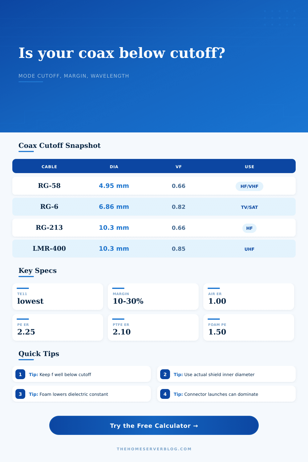
You can see in the reference table on this page why RG-58 differ from something like LMR-400 regarding these physical constraints. The thicker cable have higher power handling and less resistive loss, but cuts off at lower frequency due to modal cutoff. This is an engineering tradeoff. Smaller cables means more bandwidth but less power handling.
The cutoff frequency One important part of all of this is the dielectric material itself. Dielectrics such as solid polyethylene increases the dielectric constant and are heavier, reducing the cutoff frequency. Lighter materials like foam dielectrics decreases the constant and push it up further. PTFE increases stability but is also challenging to handle. By choosing type of cable in the tool, the system adjust for the proper dielectric constant and velocity factor.
Why does this matter? The speed of light changes through the cable versus in free space. It’s slower. That reduces wavelength, and thus the fields change. Your calculations for margin are not going to take into account that dielectric if you don’t do so.
The weak link in many high-frequency installations are the connectors. Even though you may have a perfect cable, a sloppily crimped connector or an improperly matched adapter can ruin it all. The calculator let you include counts of connectors as well as type/class. For example, BNC types introduce additional discontinuities, while N-type connectors perform better at UHF. Every joint represent additional loss and possible mode conversion. Keep runs short if building a bench test fixture where you can afford precision connectors. Account for additional losses due to adapters on a long outdoor drop.
The system performance isn’t determined solely by the cable, but rather by the whole path. Manufacturing tolerances, bends, compression issues… that’s why there is safety margins. In the perfect world, theoretical cutoff would of been a hard limit. Give yourself some breathing room with a ten or twenty percent derate. That will keep you well below the point where higher-order modes begin to excite.
You’re gambling with your signal integrity if your operating frequency is anywhere near the calculated cutoff. The tool explicitly tells you what your margin is at that frequency. You get to see exactly how much headroom you have. Risky = small margin. Safe = big margin.
The other factor is length. A longer cable has more loss (reduces signal-to-noise ratio). To get an estimate of that, I plugged in my cable type and frequency into the calculator for the total run loss. From there, it will tell you whether you might benefit from a lower-loss cable or even require an amplifier.
It links the modal cutoff with practical system design. So this isn’t just some random physics check off box. This is about putting together a working link. Respect the physical limits of coaxial cable. Understand its cutoff frequency to prevent higher-order modes from appearing unexpectedly. It’s not rocket science; it’s just a bit of math. But the insight isn’t. Send your signal as you intend it, and it’ll get there intact. This works as long as you keep your frequencies low, your connector clean, and your margins healthy.