HomeServerBlog RF antenna calculator
dBi to dBd Converter
Convert antenna gain between dBi and dBd, subtract cable, connector, and polarization losses, estimate realized EIRP, and compare common antenna choices for home lab RF links.
1Antenna presets
2Gain conversion and RF path inputs
Conversion breakdown
Planning status
3Live RF helper values
Based on the selected center band.
A half-wave dipole is 2.15 dB above isotropic.
Estimated conducted power needed.
Type-based beam planning note.
4Antenna comparison grid
5Antenna gain reference tables
| dBi | dBd | Linear gain over isotropic | Common antenna note |
|---|---|---|---|
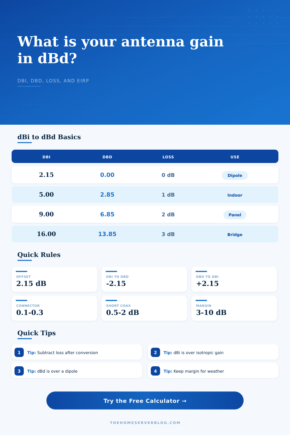
| 0 dBi | -2.15 dBd | 1.00x | Isotropic reference only, not a normal physical antenna. |
| 2.15 dBi | 0.00 dBd | 1.64x | Half-wave dipole reference point. |
| 5 dBi | 2.85 dBd | 3.16x | Small router antenna or compact indoor panel. |
| 9 dBi | 6.85 dBd | 7.94x | Outdoor omni, panel, or modest yagi range. |
| 16 dBi | 13.85 dBd | 39.8x | Directional bridge panel or higher-gain yagi. |
| 24 dBi | 21.85 dBd | 251x | Grid dish or compact microwave dish class. |
| Antenna type | Typical dBi | Typical dBd | Pattern behavior |
|---|---|---|---|
| Half-wave dipole | 2.15 dBi | 0 dBd | Broad pattern, useful as the dBd reference. |
| Rubber duck / whip | 1 to 5 dBi | -1.15 to 2.85 dBd | Portable and compact, often lossy in real installs. |
| Collinear omni | 5 to 12 dBi | 2.85 to 9.85 dBd | Wide azimuth with narrower elevation coverage. |
| Flat panel | 8 to 18 dBi | 5.85 to 15.85 dBd | Moderate directional beam for walls and short bridges. |
| Yagi | 9 to 17 dBi | 6.85 to 14.85 dBd | Directional, rugged, and common below microwave bands. |
| Dish | 18 to 34 dBi | 15.85 to 31.85 dBd | Narrow beam, high pointing sensitivity. |
| Loss item | Typical dB | Where to enter it | Effect |
|---|---|---|---|
| Short pigtail | 0.1 to 0.5 dB | Cable loss | Subtracts directly from realized gain and EIRP. |
| Outdoor coax run | 1 to 6 dB | Cable loss | Can erase much of a small antenna upgrade. |
| Two clean connectors | 0.2 to 0.6 dB | Connector loss | Small but important near an EIRP limit. |
| Lightning protector | 0.2 to 0.8 dB | Connector or other loss | Include every inline RF part. |
| Polarization skew | 0.2 to 3 dB | Polarization loss | Worse when linear antennas are rotated apart. |
| Radome or mismatch | 0.2 to 2 dB | Other RF loss | Depends heavily on material and frequency. |
| Frequency band | Approx wavelength | Common antenna | Planning note |
|---|---|---|---|
| 433 MHz ISM | 69.2 cm | Whip, yagi, collinear | Longer antennas; cable loss is modest but size matters. |
| 900 MHz ISM | 33.3 cm | Yagi or omni | Useful for lower-speed long range links. |
| 2.4 GHz Wi-Fi | 12.5 cm | Dipole, panel, omni | Indoor antennas are compact; polarization still matters. |
| 5 GHz bridge | 5.2 cm | Panel or dish | Feedline and aiming losses become more visible. |
| 6 GHz Wi-Fi | 5.0 cm | Integrated panel | Confirm device class and allowed antenna configuration. |
| 10 GHz microwave | 3.0 cm | Dish or horn | High gain is easy; alignment tolerance tightens fast. |
6Practical antenna conversion tips
Chances are you installed that high-gain antenna because of a dead zone issue. But it didn’t help much when it came to improving your signal. That’s not necessarily antenna fault. What you’re looking at is invisible math occurring between your radio and the outside air.
You may be thinking of gain numbers as absolute power levels, but in fact they refers to various theoretical standards. Getting the range you paid for begins with understanding distinction between dBi and dBd. Two conflicting zero points are at root of confusion.
Understanding Antenna Gain
Gain can be measured as dBi (gain over an isotropic radiator) or dBd (gain over a half-wave dipole). An isotropic radiator is a theoretical point source of energy that puts out equal energy in all directions. It doesn’t actually exist in reality, but it gives us a nice clean place to start when we does our math.
A half-wave dipole is a real physical antenna that has defined radiation pattern and therefore slightly more directional than the theoretical point source. That makes a dipole slightly more directional than the theoretical source; specifically, a dipole are 2.15 dBi. So basically if an antenna says it’s rated in dBi then you know the number will be larger than its dBd rating. The calculator figures this out for you, but understanding reason for the offset makes it easier to trust what it shows.
But then you’ll notice if you neglect to subtract out the losses that take away from your hypothetical increase. That gain of 16 dBi you see on a datasheet? Well, that’s under ideal conditions where everything is perfectly connected. In the real world you’ve got connectors clicking into place, coaxial cable running up the wall, maybe you’ve got polarization mismatch. All of those things weaken your signal. Attenuation is a nice way of saying they’re causing signal loss.
A three-decibel cable loss will literal cut your power in half. Sounds like an exaggeration but that’s how RF physics work. You can remove these attenuation values with the tool to calculate what your realized gain are. This is really the value that makes a difference in your link budget.
A lot of folks forget about cable thickness and length. Standard coax loses a lot of signal at higher frequencies, such as 6 GHz or even 5 GHz. You can have moderate-gain antenna but if you have short run of poor quality cable, that gain won’t do much for you. For example, it’s sometimes preferable to have low-gain antenna connected via a short run of good-quality cable (known as a pigtail) than a high-gain antenna connected via a long run of lossy cable.
That’s why the helper section includes the frequency band selection. This shows how wavelength affects the practical limitations of your system. If your wavelength is shorter, the feedline losses matter more… Each foot of cable matters more.
One other thing we hardly ever see on the box are polarization. If your receiver has horizontal antennas but your transmitter has vertical polarization, your signal won’t be as strong. No amount of claimed antenna gain will fix this. This isn’t a conversion problem. It’s a pure alignment problem. Because polarization loss is indeed a real world variable, and one that can vary tremendously from install to install, there’s a spot in the calculator for it. Maybe a couple degrees of skew won’t make much difference. But enough will cause degraded performance to the point where link may fail completly.
Effective Isotropic Radiated Power (EIRP) is what matters to regulators. EIRP combines your transmitter output with your realized antenna gain. That’s what actualy reaches a receiver and how far it can go. If your reference is dBd, and you want to know what your effective radiated power is, you need to convert to dBi, then add in your radio power. A dBi is not the same as adding power.
The Planning Status section makes it easy to see if you have plenty of room for obstacles, weather, and even time so your gear hasn’t aged out yet. A zero margin link means it will fail. Better to err on side of too much gain than to little gain.
To conclude. Choosing an antenna involves gain, bandwidth, and size. Big antennas has high gain but require careful aiming. Little antennas have low gain and are more forgiving. Go after what best fits the task, not just the spec with the biggest number. When you stop seeing gain as a selling point, and begin thinking of it as a variable in your system, things falls into place better. It’s really not complicated math, but it does take some attention when applied. That 2.15 dB offset isn’t large, but it could of made all the difference.