Collision Domain Calculator
Estimate Ethernet collision domains for switched networks, router boundaries, hub segments, repeaters, legacy half-duplex islands, and VLAN planning context.
Formula Breakdown
| Device or Link | Collision Domain Rule | Broadcast Domain Rule | Practical Note |
|---|---|---|---|
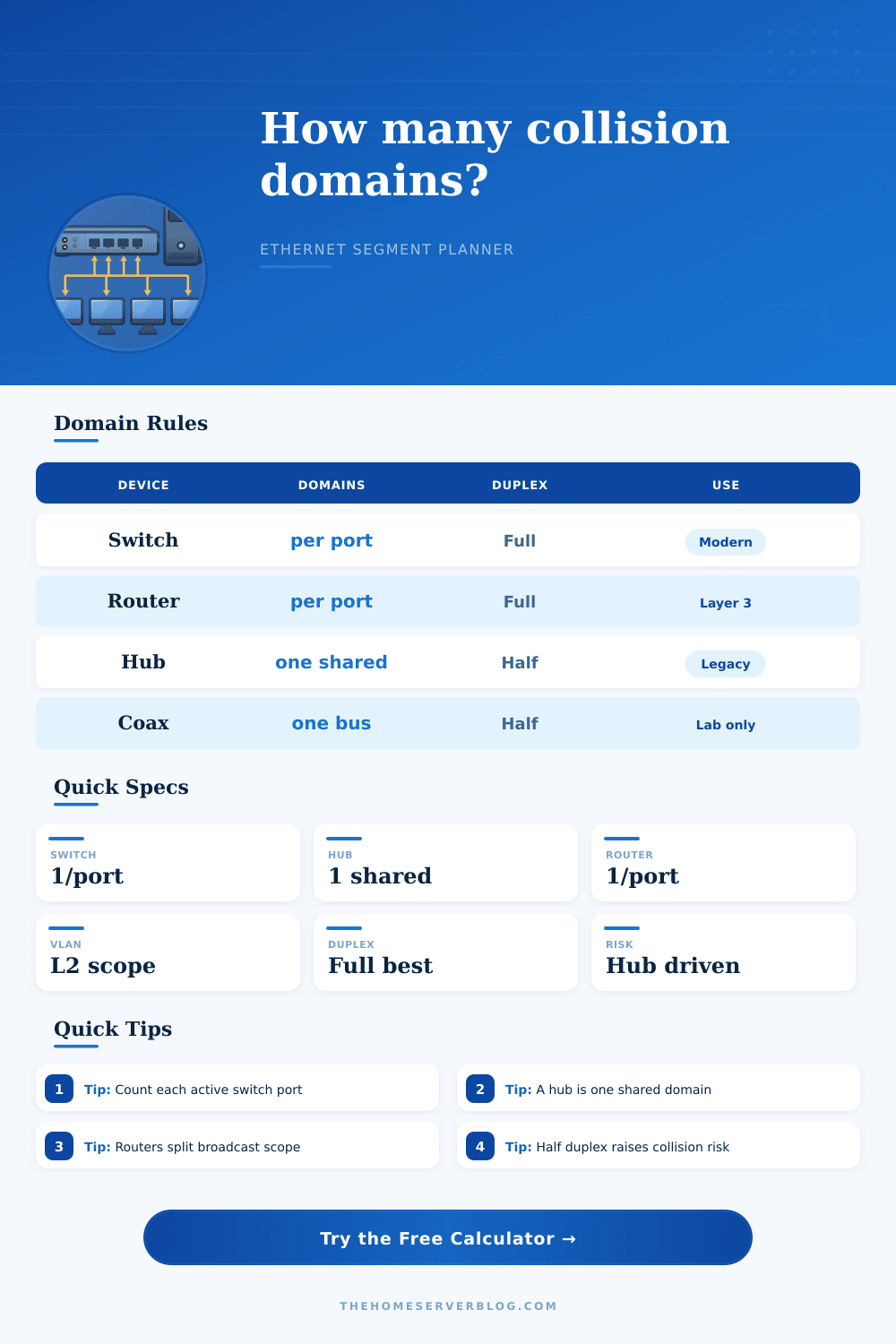
| Switch access port | One per active port | Same VLAN unless routed | Modern full-duplex links have no practical collisions. |
| Switch trunk link | One per physical link | Can carry many VLANs | The trunk is one Ethernet segment even with tagged VLANs. |
| Router interface | One per Ethernet interface | Splits broadcast domains | Layer 3 forwarding stops Layer 2 broadcast flooding. |
| Hub or repeater | One shared domain | Same broadcast domain | Adding devices increases contention, not domain count. |
| Transparent bridge | One per bridge port | Usually same broadcast domain | Useful distinction for old Ethernet diagrams. |
| Topology | Typical Domains | Legacy Risk | Interpretation |
|---|---|---|---|
| Five-port home switch | 4 to 5 | Low | Each connected device has a separate full-duplex segment. |
| 24-port access switch | 20 to 26 | Low | Count used access ports plus uplinks, not empty ports. |
| Switch with one hub | Switch ports plus 1 | Medium | The hub side is one shared collision zone. |
| Router lab | Per routed link | Low to medium | Half-duplex serial links are not Ethernet collision domains. |
| 10BASE2 coax bench | One per bus | High | All stations on the same coax share collision behavior. |
| Standard or Concept | Layer | Domain Impact | Planning Limit |
|---|---|---|---|
| CSMA/CD | Layer 2 MAC | Collision behavior | Relevant to half-duplex shared Ethernet. |
| Full duplex | Layer 1/2 | Removes collisions | Use auto-negotiation or matching forced settings. |
| VLAN tagging | Layer 2 | Broadcast scope | Does not multiply collision domains by itself. |
| Spanning Tree | Layer 2 | Blocks loops | Inactive blocked links should not be counted as active domains. |
| Routing | Layer 3 | Boundary | One routed Ethernet interface per attached segment. |
| Common Project | Equipment Count | Domain Estimate | What to Watch |
|---|---|---|---|
| Home office LAN | 1 switch, router | 6 to 12 | Unused switch ports should not inflate the count. |
| Proxmox mini cluster | 3 nodes, NAS, uplinks | 8 to 16 | VM bridges do not split broadcasts unless routed or VLANed. |
| Access point stack | PoE switch, APs | Per AP uplink | Wireless contention is separate from Ethernet collision domains. |
| Legacy class lab | Switches and hubs | Mixed | Hub segments are the risk driver. |
| Industrial cell | Bridge, PLCs | Per bridge port | Half-duplex media converters can raise risk. |
A collision domain are the number of stations that can hear the other stations transmits at the same time on the network. The way in which a network is set up will impact the number of collision domain that exist on the network. For instance, when using a moddern switch, each active port will create its own collision domain.
In contrast, if a hub is used, the hub will repeat the signal out to each port, and the device attached to the hub will each share in that same collision domain. The calculator allow a network administrator to input the number of dedicated switch ports, uplinks between switches, routed interfaces, and hub segment. Furthermore, the user can also enter the number of remaining coax link and half-duplex links into the calculator.
How to Count Collision Domains with a Simple Calculator
Based off these inputs, the calculator can separate the network into switched point to point domains, routed or bridged domains, and shared zone. Additionally, the calculator can calculate the planning buffer for the network, as well as provide a risk score for the network. The risk score will be higher if the network include half-duplex ports, as these are a form of legacy behavior.
It is easy for people to forget that the trunk link between switches will create individual Ethernet segment. These individual segments will contain their own VLANs, but the VLANs will not create their own collision domains. By leaving VLANs separate from collision domains, the calculator will help a network administrator to understand if adding a trunk link will help to reduce a bottleneck in the network, or if it will simply move the bottleneck else where.
The same principle apply to virtual machine bridges. Thus, while an uplink between machines will contain only a single Ethernet segment, a virtual switch can model its own internal segments. Despite the prevalence of moddern switch technology, some legacy network equipment, like hubs, may still be in use.
For instance, an network that is otherwise composed of switches may have a single hub that is connected to the rest of the network. This single hub will create one shared collision domain for the network. Furthermore, the presence of that single hub will increase the risk score for the network.
However, replacing that hub with a switch will increase the number of available collision domains, as well as eliminate the contention between device on that network. Similarly, any network that has a half-duplex port will introduce the potential for late collision into the network. These late collisions will only impact the link to the single device that has that half-duplex port.
Any percentage of half-duplex ports will increase the risk score for the network. The tables provides the classic rules for collision domains and broadcast domains. For instance, the tables indicate that a router port will split collision domains and broadcast domains, but a transparent bridge will only split collision domains.
Furthermore, the tables indicate that regardless of the length of the coax segment, all segments are still one single domain sharing the same medium. These distinctions should of been remembered, as otherwise, it is easy for network administrator to count the number of physical ports on a switch rather than the number of active switch links. Networks change over time.
For instance, adding a new server or machine will require a new cable to connect the device. Furthermore, each new cable will create another segment for the network. Thus, network administrator should only count the number of cables in use.
Furthermore, the network calculator can help network administrators to understand how using a hub or using a media converter will affect the network. A change in the risk score will indicate whether or not the convenience of the change in the network is worth the increase in network contention. Thinking about collision domains can help to understand the cause of network performance problems.
For instance, if there are late collision on a switch port, a duplex mismatch may be the cause of the problem, as may a cable fault. Furthermore, if four device are connected to a hub, the hub may be able to manage the collision domains well, but the hub may start to drop frame if a fifth device joins the network using that hub. Finally, while not a replacement for using packet capture software to diagnose the network, the collision domain calculator is one way to determine where packet capture will most likely reveal network problems.
For instance, each time that a network administrator becomes aware of a new connection to a network, the administrator will either have to recognize that it created another collision domain, or that it became another device in a shared collision domain. Thus, if any change are made to the hardware component of the network, such as replacing an aging hub, it will be immediately obvious which problems will be eradicated.