HomeServerBlog RF, audio, and network calculator
dB Gain to Linear Calculator
Convert dB gain into power or voltage ratios, cascade multiple stages, subtract feedline and noise penalties, and estimate output level for RF links, audio chains, coax runs, and lab measurements.
1RF, audio, and network presets
2dB gain and chain inputs
Calculation breakdown
Chain status
3Derived gain snapshot
Main stages plus additional cascaded gain.
Cable, other losses, and noise figure.
Full chain converted after dB summing.
Net gain compared with the target value.
4RF chain comparison grid
5dB conversion tables
| dB gain | Power ratio | Power percent | Common interpretation |
|---|---|---|---|
| -30 dB | 0.001x | 0.1% | Large attenuation or strong splitter/filter loss. |
| -20 dB | 0.01x | 1% | One percent power remains after the loss. |
| -10 dB | 0.10x | 10% | Tenfold power loss, common fixed pad value. |
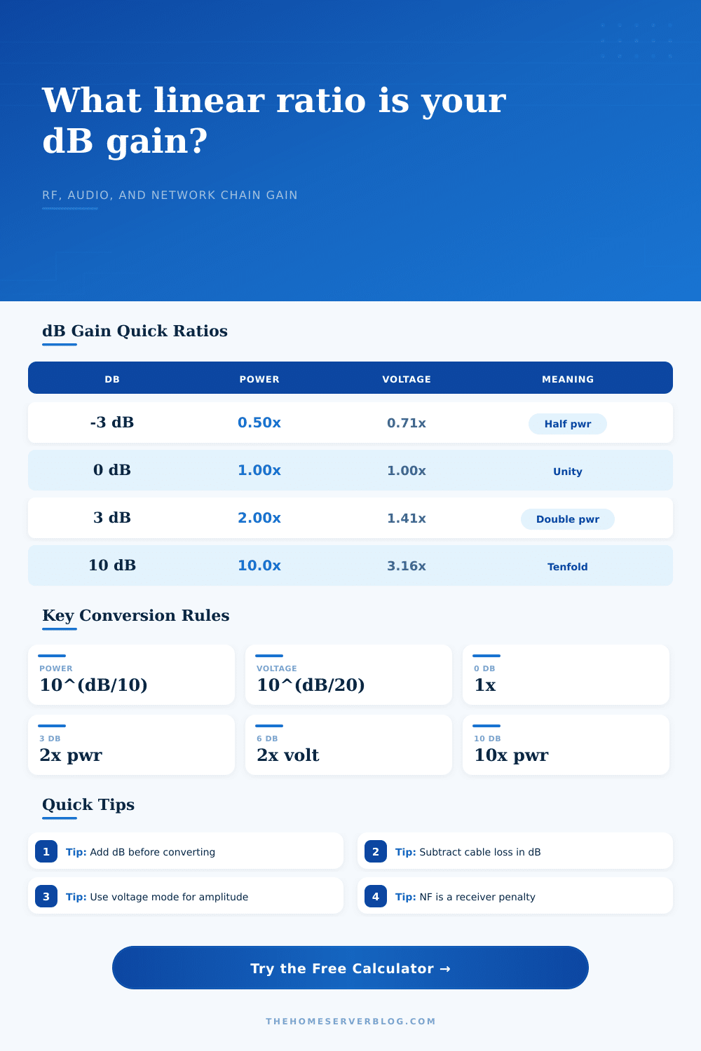
| -3 dB | 0.50x | 50% | About half the power remains. |
| 0 dB | 1.00x | 100% | Unity gain with no power change. |
| 3 dB | 2.00x | 200% | About double the power. |
| 10 dB | 10.0x | 1000% | Tenfold power gain. |
| 20 dB | 100x | 10000% | Two decades of power gain. |
| 30 dB | 1000x | 100000% | High RF amplifier or antenna system gain. |
| dB gain | Voltage ratio | Amplitude percent | Common interpretation |
|---|---|---|---|
| -40 dB | 0.010x | 1% | Very deep pad, mute trim, or measurement scaling. |
| -20 dB | 0.100x | 10% | Tenfold voltage reduction. |
| -6 dB | 0.501x | 50% | About half the voltage amplitude. |
| -3 dB | 0.708x | 70.8% | Half power into the same impedance. |
| 0 dB | 1.000x | 100% | Unity voltage gain. |
| 6 dB | 1.995x | 199.5% | About double the voltage. |
| 20 dB | 10.0x | 1000% | Tenfold voltage or amplitude gain. |
| 40 dB | 100x | 10000% | Large preamp or instrumentation gain. |
| RF component | Typical dB | Linear effect | How to enter it |
|---|---|---|---|
| Low-noise amplifier | 10 to 25 dB | 10x to 316x power | Enter as dB gain and stage count. |
| Panel antenna | 5 to 18 dBi | 3.2x to 63x power | Enter as antenna gain dBi. |
| Short coax patch | 0.3 to 2 dB | 7% to 37% loss | Enter as cable loss dB. |
| Long coax feed | 3 to 12 dB | 50% to 94% loss | Enter as cable loss dB. |
| Two-way splitter | 3.5 dB | 55% loss | Enter as other losses dB. |
| Receiver noise figure | 1 to 8 dB | quality penalty | Enter as noise figure dB. |
| Domain | Reference style | Useful dB range | Practical note |
|---|---|---|---|
| RF receive chain | dBm and dBi | -20 to +40 dB | Sum antenna, LNA, cable, filter, and NF terms before converting. |
| Coax distribution | dBmV or power ratio | -20 to +20 dB | Splitters, taps, and coax loss usually dominate net level. |
| Audio line level | dBV, dBu, V RMS | -40 to +40 dB | Use voltage mode for gain staging and level trims. |
| Ethernet PHY margin | ratio or percent | -10 to +10 dB | Small insertion losses can be easier to compare as dB first. |
| Optical module path | dBm and loss budget | -30 to +10 dB | Power ratios help explain link budget headroom. |
6Practical dB conversion tips
If you’ve ever read a spec sheet that shows gain in decibels and wondered how much power that actualy is in watts, you have likely run into this problem before. Many signal chain fail simply because the design engineers don’t understand how to bridge linear reality with their logarithmic math. Those +dB numbers lead you to believe you has plenty of headroom when, by the time the signal reach the receiver, it’s lost in the noise floor.
The converter tool above handles the translation for you so you do not need a scientific calculator for every splitter or patch cord. It converts those abstract dB figures to something intuitive: ratios. This is really just an example of how our brains are ill-equipped to think in exponents. A change of 10 dB is closer to triple then double. It is exactly ten times as much in power, or about 3x in voltage.
Why You Need This Calculator
Because of this, we tend to budget things too optimistically based off what sounds good rather than being realistic. That’s where the calculator helps. It lets you plug in your gain/loss numbers in series and shows you the compounded result. To do this, it adds the gains and losses in dB together (the right way to combine multiple component) and then converts them back to a linear ratio before you see the final number. So it won’t let those round-off errors creep into calculation from multiplying and converting each time.
For example, think about a simple audio chain such as your audio mixer, or your Wi-Fi set-up. There’s a splitter reducing the signal strength; there’s a cable weakening it further; there’s an amplifier boosting it again. In each case, the data sheet tells you this value in decibel terms. Try mentally converting all these to percentages, multiplying, and seeing what happens: you’re either going to get it wrong, or give up!
Instead, with this interface you can type in overall gain, then deduct for cable attenuation and account for connector losses, then apply the receiver’s noise figure, which is usually ignored, but which represents an actual penalty against your signal-to-noise ratio, effectively reducing system gain.
The key to answering this correctly involves understanding whether the question is asking for voltage or power ratios. For example, if the antenna system or RF link is measured in watts, then it’s the power ratio (divisor of 10 in the exponent). Or if it’s about sensor voltages or audio line levels, then it’s the voltage ratio (divisor of 20, since power scales as the square of voltage). Failing to understand this will result in your answer being off by the square root of the correct answer, which can be quite large if you’re doing precision engineering. The tool includes presets to guide you toward the right setting: either a studio headphone amplifier setup or troubleshooting an LTE modem path.
And then there’s the issue of reference levels. What good is a gain of 20 decibels if you don’t know what you’re gaining it from? The calculator allows you to enter a level as an input, either line-level voltage (from a mixing console) or dBm (the weaker signal arriving from a distant tower). Then it calculates the output level when all those gains and losses are factored in. This allows you to double-check your signal level. You can make sure it isn’t too low for the receiver to pick up or too high and clip the input stage of the receiving device. It takes a theoretical gain number and turns it into a practical prediction of system performance.
Most folks don’t realize how much longer lengths of coax and higher frequencies increase cable loss. While a short patch cord may not have any measurable loss, a long run of coax at high frequencies can eat up most your link budget. You can enter that loss directly into the tool so that instead of getting some idealized best-case guess at net gain, you’ll get a realistic estimate. You can also enter in what your actual components are for comparison to your desired gain margin. So if you’re building out a system that needs to maintain a certain minimum signal strength, you’ll know instantly whether or not your component selections will make the cut.
For common numbers, there are some quick reference points on the page in the form of tables. It reminds us that zero dB is unity, three dB is about twice the power and ten dB is ten times the power. Think of those as anchor points to mentally remember the relationship. If we see -3 dB, then we have lost half our signal. If we see +12 dB, then we know it’s just over twice the power. This helps you understand the calculator’s results a little easier and feel more confident with them.
In summary, this is all about taking those decibel readings and turning them into something useful. It is going from knowing that a part exists to knowing if that part works for your system. Use the calculator at the top of this article to do the math for you. But in order to understand what those results say, you need to know the story of the signal itself. Know where the input starts, figure out how much gets lost as it goes through various components, and see if the resulting output sounds like it suits your purpose. The magic lies in knowing what you are really measuring, then letting the math show you the rest.