PoE Cable Heating Calculator
Estimate PoE copper heating, cable temperature rise, voltage loss, bundle derating, and pass/fail margin for home lab switches, cameras, access points, phones, and high-power 802.3bt runs.
PoE cable heating result
| Cable conductor | Typical resistance | PoE heating note | Common use |
|---|---|---|---|
| 26 AWG | 40.8 ohm / 1000 ft per conductor | Highest heating and voltage drop in thin patch cords. | Short rack patches, not dense long PoE bundles. |
| 24 AWG | 25.7 ohm / 1000 ft per conductor | Baseline copper for many Cat5e and Cat6 permanent links. | Typical home lab cameras, phones, and APs. |
| 23 AWG | 20.4 ohm / 1000 ft per conductor | Lower I-squared-R loss, useful for PoE+ and PoE++ channels. | Cat6, Cat6A, riser, plenum, longer drops. |
| 22 AWG | 16.1 ohm / 1000 ft per conductor | Best copper margin in this calculator, but check connector fit. | Specialty PoE, industrial, and high-temperature cable. |
| PoE class | PSE power | Powered pairs | Heating behavior |
|---|---|---|---|
| IEEE 802.3af Type 1 | Up to 15.4 W at PSE | 2 pairs | Usually modest heating unless cables are very thin or tightly bundled. |
| IEEE 802.3at Type 2 | Up to 30 W at PSE | 2 pairs | Noticeable copper loss on long 24 AWG channels and medium bundles. |
| IEEE 802.3bt Type 3 | Up to 60 W at PSE | 4 pairs | Four-pair feed shares current, but dense bundles still need review. |
| IEEE 802.3bt Type 4 | Up to 90 W at PSE | 4 pairs | High current and high bundle count can push cable temperature limits. |
| Pathway condition | Thermal multiplier | Risk trigger | Planning response |
|---|---|---|---|
| Open rack or ladder tray | Lowest | Long high-current runs grouped near switch exits. | Comb, spread, and route high-power ports apart. |
| J-hooks or loose bundle | Moderate | More than 24 continuously powered cables. | Split bundles and avoid tight hook fill. |
| Conduit or sleeve | High | PoE+ or PoE++ cables in long enclosed sections. | Lower fill, shorten conduit, or derate current. |
| Insulated attic cavity | Highest | High ambient temperature plus poor heat rejection. | Use higher rated cable and conservative rise limits. |
| Temperature checkpoint | What to compare | Why it matters | Calculator field |
|---|---|---|---|
| Ambient temperature | Ceiling, rack, attic, conduit, or tray air temperature | It adds directly to cable heating rise. | Ambient temperature C |
| Allowed rise | Owner, standard, or manufacturer rise limit | Keeps the center of the bundle below a chosen limit. | Allowable temperature rise C |
| Jacket rating | 60 C, 75 C, or 90 C cable rating | Final cable temperature should stay below jacket limits. | Cable jacket temperature rating C |
| Derating factor | Manual safety factor for unknowns | Converts a marginal calculation into a conservative design check. | Manual derating factor percent |
For example: You install a PoE camera in the parking lot and run the PoE cable from there back to the server room. For a week, it’s all good. Every Tuesday afternoon, however, the footage start glitching. You recheck the firmware. You recheck the switch ports. You even blame the weather. But nope, the villain is right there in the ceiling space. And its overheating.
When you use power over ethernet, your network cabling becomes a heating element. It conducts both data AND watts. Those watts create heat which is then confined to one place: the copper itself. Voltage drop occur, starving your devices at the worst possible time. Mostly the issue isnt the cable itself, but the bundle. If you have twenty-four cables stacked up in a tight tray or conduit they become their own insulators. They stop any airflow and the core of your bundle acts like a thermal battery.
Why PoE Cables Get Hot
Run the math yourself with the calculator above, but know this: Intuition is what matters. Learn to understand that it’s not just the power, but the confinement that causes heat rise. A single cable by itself in open air can cool off readily enough. But if you wrap it around three other ones and then shove them all in a plastic sleeve? No breathing. Holding the energy. Getting hot. The end point starve.
First, consider the gauge. Twenty-six AWG patch cords is just fine unless you push 30 watts of anything through them. At that point, the resistance is high and the I-squared-R losses becomes waste heat. People make this mistake. They purchase cheap patch cables for permanent links and then expect the same performance as Cat6 from wire that’s barely thick enough to handle a phone signal. Upgrading to twenty-three AWG or heavier copper will make a noticeable difference. Thicker conductors has lower resistance. Lower resistance equals fewer losses in heat. Fewer losses in heat equal better margins. Simple physics. Often overlooked until the lights go out.
And what about the path? It looks neat and has a good fire rating, but its thermodynamics are awful. Every joule of waste heat gets trapped inside a sealed sleeve. To account for this, the model use multipliers for how things is installed. For example, an open ladder tray allow heat to dissipate. An insulated attic cavity then amplifies that heat. You might be running PoE++ lighting drivers or high-powered access points. Where the switch is chosen matter as much as the path taken. Best copper in the world won’t do you any good when buried inside a thermal coffin.
Another factor is ambient temperature. Thirty degree Celsius ambient on the rack is already a bad start. Then add in fifteen degrees from that bundle of cables. Now you’re up to forty-five degrees right where the connector plug into the jack. Usually, no problem there. But increase that ambient temperature (or pack more dense bundles) and you exceed the ratings of the jacket. So it degrades the insulation, which degrades the contacts, which degrades the signal. And your signal integrity goes south.
The calculator help you see that threshold before you pull the cable. With the calculator, you can see what that number is ahead of time. Because it’s the worst case model. You don’t have to learn it on the fly in a thunder storm.
This goes back to what I said above about not paying attention to the heart of the bundle. Those inside gets cooked and those out on the edges cool a bit. So if you just barely squeak by on the outside, then it will fail in the center. By derating your power a bit (ten or twenty percent) you are insuring yourself. It is cheap insurance. That margin you saved on packing an extra cable in that tray could of cost less than a failed port.
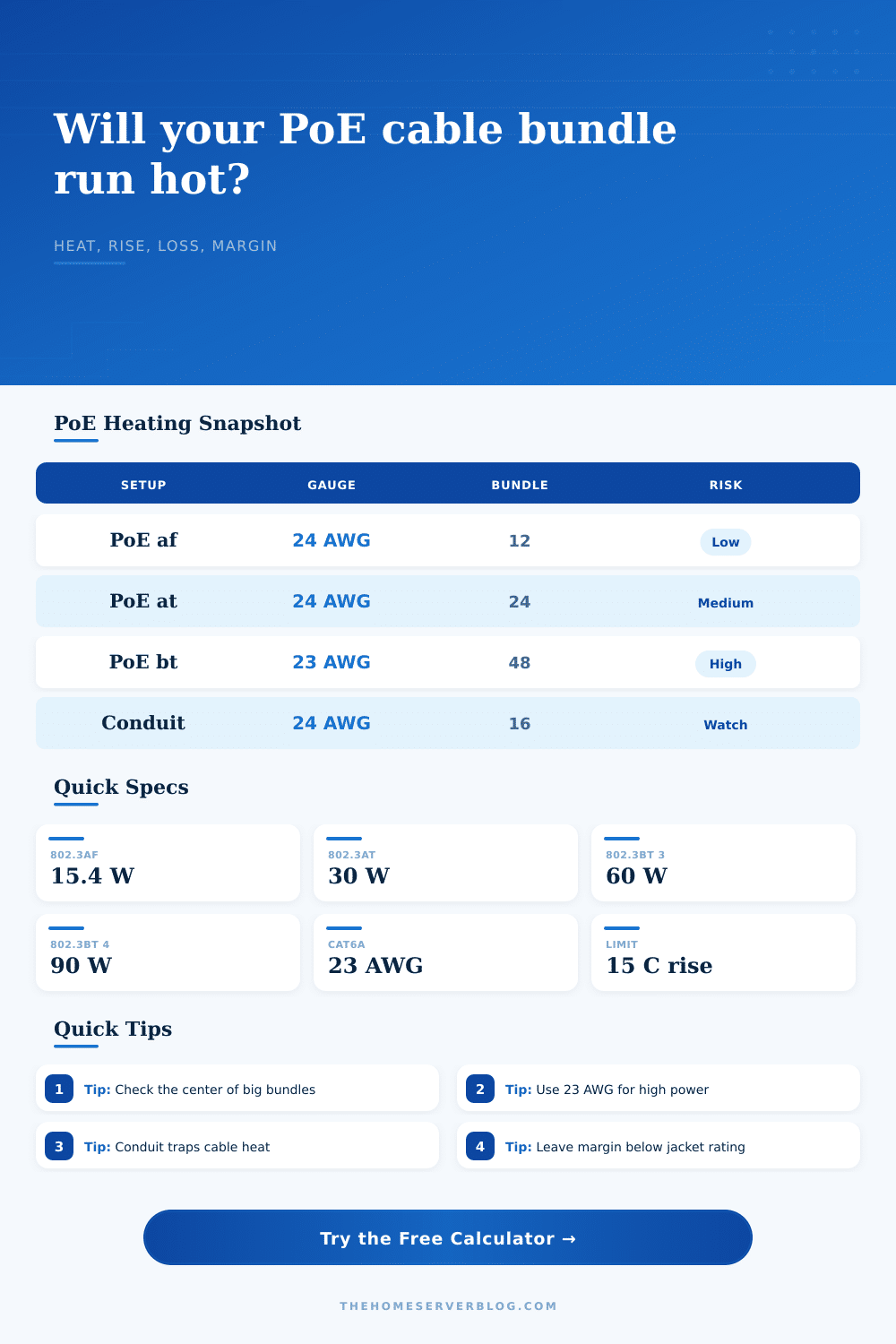
Look at the tradeoff tables on the page. Those lay out the tradeoffs nicely. And they illustrate why Type 4 power require some serious planning. And they illustrate why twenty-four AWG is a baseline for discussion, not a hero. Use them. Let them guide you.
Plug in numbers without understanding what they are? That’s a recipe for ruining your day. Voltage drop isnt something that makes noise; heat isnt something that you can see. But they’ll ruin your day if you don’t pay attention to it.
Consider your cabling like a plumbing system. If I ran a firehose through a garden hose, what would happen? Would I put high pressure on a small pipe? It’d burst in no time flat. Do the same with power. Use the appropriate gauge for the load. Provide some room for it to breathe. Allow it space. Don’t use a link just because it will work. Use one that will survive.
Keeping the voltage steady and keeping the center cool are good things. Your endpoint will be glad you did.