Dipole Antenna Gain Calculator
Estimate broadside gain, feedpoint impedance, and 2:1 bandwidth for HF, VHF, and portable dipole builds.
Full Breakdown
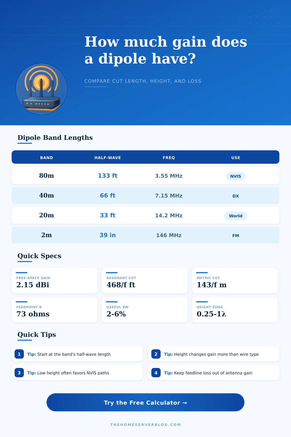
| Band | Half-wave | Freq | Typical use |
|---|---|---|---|
| 80 m | 133 ft | 3.55 MHz | NVIS |
| 40 m | 66 ft | 7.15 MHz | General DX |
| 20 m | 33 ft | 14.2 MHz | Worldwide |
| 2 m | 39 in | 146 MHz | FM / local |
| Height | Offset | Angle | Pattern note |
|---|---|---|---|
| 0.05 λ | -1.6 dB | 85 deg | Strong NVIS |
| 0.25 λ | +0.6 dB | 60 deg | Good compromise |
| 0.50 λ | +1.8 dB | 42 deg | Broadside lift |
| 1.00 λ | +3.0 dB | 28 deg | More low angle |
| Gauge | Dia | BW trend | Comment |
|---|---|---|---|
| 22 AWG | 0.64 mm | Narrow | Light field wire |
| 18 AWG | 1.02 mm | Medium | Good all-round |
| 14 AWG | 1.63 mm | Wider | Common station wire |
| 10 AWG | 2.59 mm | Very wide | Heavy duty span |
| Ground | Gain trim | Z trim | Practical note |
|---|---|---|---|
| Open yard | +0.1 dB | 0 ohm | Clean reflection |
| Suburban | -0.1 dB | +3 ohm | Moderate clutter |
| Rooftop | -0.4 dB | +8 ohm | Metal nearby |
| Wet soil | +0.3 dB | -2 ohm | Low-angle help |
This calculator keeps geometry, ground interaction, and line losses separate so you can compare practical dipole builds without guessing at the pattern.
A dipole antenna is a type of wire antenna that you can hang between two point in order to facilitate radio communication between two points. The performance of a dipole antenna are influenced by many different factor, but three factors specifically determine the performance of a dipole antenna: the height of the dipole antenna, the length of the dipole antenna, and the surroundings of the dipole antenna. The gain of a dipole antenna is a measurement of the strength of the signal that that antenna emits.
Furthermore, the gain of that antenna will determine whether or not the antenna can communicate with a distant radio station, or if it will only emit static signal. The height at which a dipole antenna is hung will change the way in which the antenna radiates the signal. A half wavelength dipole antenna will have a gain of 2.15 dBi when measured in free space.
Things that affect a dipole antenna
If the antenna is hung low, such as at a height of one-twentieth of a wavelength, the signal will be reflected off of the ground, squashing the radiation of the signal to the sky. This is useful for Near Vertical Incidence Skywave (NVIS) communication, but is not useful for long distance (DX) communication. However, if the antenna is raised to a height of one-half of a wavelength, the gain of the antenna will increase, and the take-off angles of the signal will be more suitable for DX communication.
For these reasons, many who use dipole antennas will utilize trees or masts to raise the height of the antenna to which they is connected. The type of wire that people use to construct the antenna will also affect the functioning of the dipole antenna. For example, if bare copper wire is used, it will resonate according to an 468/f formula.
Any wire that include PVC insulation, or any wire that is made of stranded wire will have a different velocity factor for its signal. As a result, the wire will be shorter than calculated with the 468/f formula, but it will have an increased bandwidth and reduced efficiency. Furthermore, the gauge of the wire will also affect the antenna.
For example, a 14 AWG wire will allow for a wider spectrum of frequencies to travel through the antenna than a 22 AWG wire. However, the 22 AWG wire will be lighter when portable antenna are constructed. Additionally, the type of feedline that is used for the antenna will cause some signal loss with the antenna; the longer the feedline, the more signal loss will occur.
The impedance of a dipole antenna is 73 ohms when the antenna is at resonance. The impedance of the antenna will change, however, if someone changes the height of the antenna, or if the angle of an inverted V shaped dipole antenna is altered. Due to these changes in impedance, a tuner may be required for the antenna.
The ground upon which the antenna is mounted will also have some effect on the antenna. For instance, if the ground upon which the antenna is mounted becomes wet, it may boost the radiation angles that travel at low degrees from the antenna. Metal on the rooftop, however, may detune the antenna.
Additionally, if the antenna is a sloper antenna, it will have a bias in one direction of radiation rather than being even in all direction. Many people makes the mistake of attempting to maximize the gain of their dipole antenna. However, if an individual desires to use NVIS communication, they should hang their antenna low.
In contrast, they should hang their antenna high if they wish to communicate with radio signals that are located at considerable distances from the antenna. For example, a 40-meter garden dipole or a 20-meter inverted-V dipole antenna will exhibit these feature. Additionally, those building a dipole antenna must ensure that the antenna is constructed in a way that avoid the introduction of common-mode current; otherwise, the antennas symmetry will be destroyed.
Thus, an individual must ensure that the antenna is cut to the correct length, that the antenna is elevated to the correct height, and that they account for the signal loss that will occur in the feedline that connects the antenna to the radio station. You should of considered that there is alot of variables to manage.