Patch Antenna Gain Calculator
Estimate realized gain, beamwidth, resonant frequency, and EIRP for patch designs with practical feed and material losses.
Full Breakdown
| Material | Er | Tan D | Best Use |
|---|---|---|---|
| FR-4 | 4.35 | 0.0200 | Budget 2.4G |
| Rogers 4350B | 3.48 | 0.0037 | Stable RF |
| Rogers 5880 | 2.20 | 0.0009 | Low loss |
| Ceramic-loaded | 6.15 | 0.0020 | Compact patch |
| Band | Patch Size | Gain | Notes |
|---|---|---|---|
| 868-915M | 90x70mm | 6-8 dBi | Large patch |
| 2.4G | 42x33mm | 6-8 dBi | Wi-Fi class |
| 3.5G | 28x22mm | 7-9 dBi | CBRS panel |
| 5.8G | 21x16mm | 7-9 dBi | WISP use |
| Layout | Elems | Gain | Beamwidth |
|---|---|---|---|
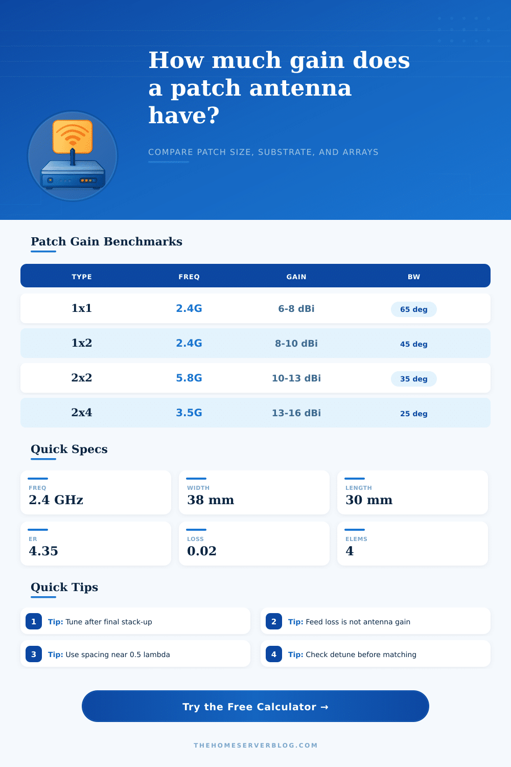
| Single | 1 | 6-8 dBi | 60-90 deg |
| 1x2 strip | 2 | 8-10 dBi | 35-60 deg |
| 2x2 square | 4 | 10-13 dBi | 25-45 deg |
| 2x4 panel | 8 | 13-16 dBi | 18-30 deg |
| Loss Item | Typical dB | Effect | Note |
|---|---|---|---|
| Feed line | 0.3-2.0 | EIRP down | Keep short |
| Radome | 0.2-1.0 | Gain down | Check cover |
| Mismatch | 0.5-3.0 | Realized loss | Detune hurts |
| Design margin | 0-20% | Conservative | Build slack |
This calculator separates antenna physics, panel geometry, and system losses so you can see where a patch design is winning or losing gain.
A patch antenna is a type of antenna that has a flat radiating element and is used for wireless communication tasks. Patch antenna can be used for a variety of different application. Patch antennas is typically use for rooftop Wi-Fi links and Internet of Things sensor.
A single patch antenna will radiate a broad beam of wireless signal, and typically provide a gain between 6 and 8 dBi. However, if a designer use an array of patch antennas, such as a 2×4 array of patch antennas, the array will provide higher gain between 13 and 16 dBi. The advantage of using an array of patch antenna compared to a single patch antenna is that the array provides a narrower beam of radiation, but has the advantage of providing a longer range of signal transmission.
Patch Antenna Basics and What Affects Performance
The size of the patch antenna is relate to the dielectric constant of the substrate on which the antenna is formed. The dielectric constant affect the wavelength of the signal that is radiated from the antenna. A higher dielectric constant will allow for a smaller physical size of the antenna, but can allow for more signal losses.
The substrate on which the patch antenna is formed is an important design consideration as it will impact the efficiency with which the patch antenna radiates its signal. Substances such as FR-4 are commonly used substrates as they are relatively inexpensive. However, the high loss tangent of the FR-4 substrate reduce the efficiency of the patch antenna.
Rogers 5880 substrates have a lower loss tangent then FR-4 substrates, and, therefore, allow for higher efficiency of the patch antenna. The thickness of the substrate impact the performance of the patch antenna; thicker substrates allow for a higher bandwidth of the antenna, but reduce the directivity of the radiated signal. The spacing between the elements of an array of patch antennas is another important design consideration.
Patch antenna array elements should be spaced around 0.5 lambda in distance from each other to avoid the formation of grating lobes, which can lead to signal reflections. Grating lobes should be avoided as they reduce the gain of the antenna; maintaining element spacing around 0.5 lambda helps to focus the energy radiated from the patch antenna. There are various sources of loss that can reduce the efficiency of a patch antenna.
One source of loss is through the feed lines that feed signal energy to the patch antenna elements. Radomes, which are protective covers for antennas that may be exposed to weather condition can also introduce losses into the system. Other sources of loss can be introduced by metal objects in the vicinity of the patch antenna; these metals will cause detuning of the patch antenna, which also reduce its efficiency.
The radiation efficiency of a patch antenna is typically between 70% and 85%. However, efficiency can decrease due to the use of surface wave and spillover. The frequency of the signal that a patch antenna transmits impact the physical dimensions of that antenna.
Additionally, the frequency impact the type of material that are required for the substrate on which the antenna is formed. Patch antennas that are to be use at 900 MHz will have a larger physical size than patch antennas designed to operate at 5.8 GHz. The high frequency of the 5.8 GHz patch antenna allow for the antenna to be physically smaller; however, the smaller size of the antenna means that a low-loss laminate substrate is require to radiate the signal efficient.
Plastic covers can also impact the performance of a patch antenna; plastic covers can shift the resonance frequency of the patch antenna by 10 to 20 MHz. Therefore, if a designer use a plastic cover for the patch antenna, the patch antenna must be tuned after the plastic cover is added to the structure. Finally, it is also important to calculate the Effective Isotropic Radiated Power (EIRP) of the antenna to ensure that the antenna meets the regulations for that particular application.