Phased Array Antenna Gain Calculator
Estimate broadside gain, scan loss, and EIRP for rooftop panels, radar tiles, and compact beam-steering arrays.
Full Breakdown
| Band | Wavelength | Safe Spacing | Typical Use |
|---|---|---|---|
| 2.4 GHz | 12.5 cm | 0.5 lambda | Mesh panel |
| 5.8 GHz | 5.2 cm | 0.5 lambda | PtP backhaul |
| 10 GHz | 3.0 cm | 0.45 lambda | Roof link |
| 28 GHz | 1.1 cm | 0.40 lambda | mmWave CPE |
| Mode | Count Rule | Area Rule | Best For |
|---|---|---|---|
| Rectangular | Rows x cols | Width x height | Broadside panels |
| Linear | Elements only | Length x strip | Slim mounts |
| Circular | Rings x ring set | Disk area | Compact tiles |
| Conformal | Arc element count | Arc span area | Curved surfaces |
| Angle | Cosine Loss | Extra Margin | Comment |
|---|---|---|---|
| 0 deg | 0.0 dB | None | Broadside peak |
| 15 deg | 0.3 dB | Light | Usually safe |
| 30 deg | 1.2 dB | Moderate | Watch spacing |
| 45 deg | 3.0 dB | Strong | Gain falls fast |
| Preset | Mode | Count | Gain Target |
|---|---|---|---|
| 2.4 Mesh | Rectangular | 16 el | About 16 dBi |
| 5.8 Backhaul | Linear | 16 el | About 17 dBi |
| 24 Radar | Circular | 24 el | About 20 dBi |
| 28 mmWave | Sparse | 50 el | About 28 dBi |
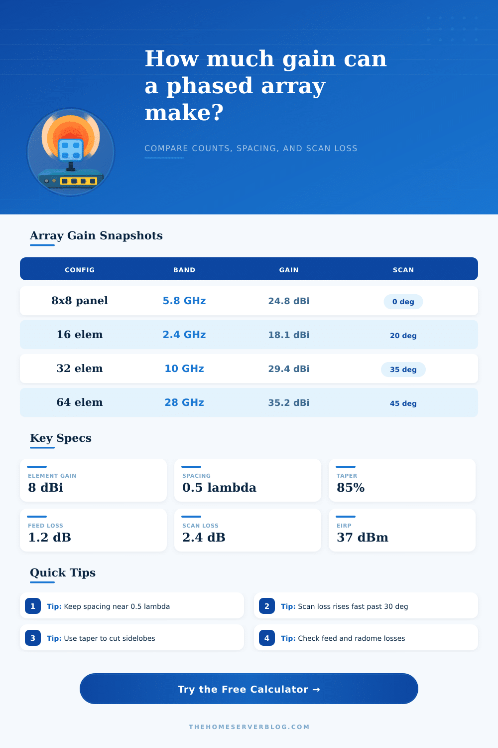
This calculator compares count-based gain and aperture-based gain so you can spot steering penalties, feed loss, and grating risk early.
When designing a phase array antenna for a 5.8 GHz backhaul link, you has to determine the numbers of antenna elements your phased array antenna will have to achieve the gain that your backhaul link requires. A phased array antenna contain many antenna element to focus the antenna’s energy into a beam without having to move the antenna. However, focusing the antenna’s energy into a beam cause losses in the gain of a phased array antenna.
The number of antenna elements, the steering angle of the antenna elements, and the physical sizes of the antenna will impact the gain of the phased array antenna. A phased array antenna produce its gain through two different methods. The first method is adding more antenna elements to the phased array antenna.
How to Choose Antenna Elements and Size for a 5.8 GHz Backhaul Link
Adding more antenna elements will increase the gain of the antenna. However, you cant add an infinitely number of antenna elements to a phased array antenna because the physical size of the antenna will limit the gain of the antenna. Rectangular panels makes use of rows and columns of antenna elements to create the aperture of the antenna.
Linear strips of antenna elements is spaced apart along a boom to create the aperture of the antenna. Additionally, circular ring and sparse tiles use different factors to account for the gaps between antenna elements within the rings and tiles, and conformal arcs use curved antenna element to conform to the shape of the object upon which they is mounted. The physical size of the antenna will limit the gain of the antenna so the antenna aperture size must be considered when adding antenna elements to a phased array antenna.
The frequency at which a phased array antenna emit its signal will determine the wavelength of the signal. The wavelength of the signal will determine the distance apart of the antenna elements of the antenna. The distance apart of the antenna elements should be approximately half of the wavelength of the signal.
If the distance between the antenna elements is too far apart, grating lobe will occur that will split the antenna’s beam and reduce the efficiency of the antenna’s beam. When a phased array antenna beams at an angle instead of in the broadside direction of the antenna, the antenna will lose gain due to cosine loss. The larger the angle of the beam of the phased array antenna, the more greater the loss in gain.
To reduce the strength of the sidelobes that radiate from a phased array antenna, taper efficiency is employ. However, the use of taper efficiency will also reduce the gain of the phased array antenna. Feed losses and radomes can also reduce the gain of a phased array antenna by 2 to 3 decibels.
There are many types of gain that affect the performance of a phased array antenna. The broadside gain is the gain that the antenna will reach when it radiate its signal in the broadside direction of the antenna. The scanned gain is the gain of the phased array antenna when the beam of the antenna is steer to a certain angle.
The effective aperture of a phased array antenna is the physical area of the antenna after accounting for the losses of the antenna system. The Effective Isotropic Radiated Power (EIRP) of a phased array antenna is the measure of the power of the antenna that is radiated in all directions. This value can be used to ensure that the phased array antenna is operating within the regulatory requirement for radio frequencies.
Many people makes mistakes when they design a phased array antenna. One of the mistake that many people make is adding more antenna elements to the antenna without increasing the physical size of the antenna aperture. Adding more antenna elements will increase the gain of the antenna until it reach the gain that is provided by the physical size of the antenna aperture.
After this point, adding more antenna elements will only increase the cost of the phased array antenna without increasing the range of the signal. Another mistake that many people make is ignoring the scanning angle of the antenna during the early stage of the design process. At broadside angles, phased array antennas may look efficient but lose 3 dB or more of gain when steer to an angle of 45 degrees.
Finally, environmental factor affect phased array antennas. Exposure of a phased array antenna to rain can increase the radome loss of the antenna. High heat can also degrade the phase shifters of a phased array antenna over time.
Using a tool that simulates the impact of environmental factors on the phased array antenna can show the impact of the fill factor and the steering angle of the antenna on the gain of the antenna. Gain, the margin of the performance of a phased array antenna, can determine if the link created by the antenna will be a stable link or a failing link. It’s important to remember that the antenna’s performance depend on many things.
You should of checked the design multiple times. Most designers dont recieve perfect results on the first try. To get the best result, you need to check the antenna’s size and its placement.
If you want to achieve better results, you must use moddern tools to simulate the design. One common problem is when the antenna’s gain is not as high as you thought. This happens more often than you’d think.
It is a common mistake to use a too small aperture, which will be a problem for your backhaul link.