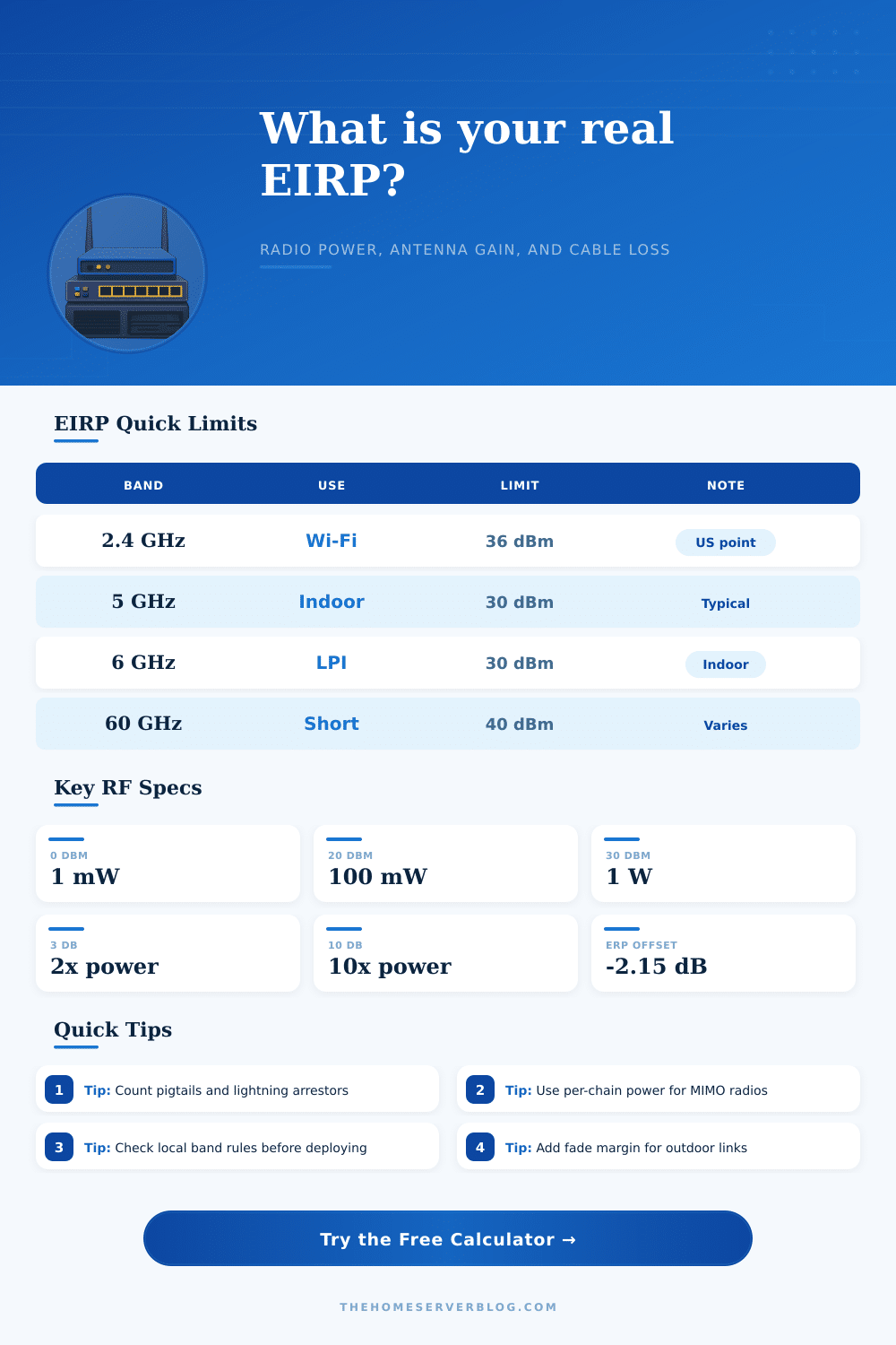
EIRP Calculator
Convert transmitter output, antenna gain, cable loss, connector loss, and path distance into real emitted power and link budget.
Calculation Breakdown
| Power | dBm | mW | Watts |
|---|---|---|---|
| Very low IoT radio | 10 dBm | 10 mW | 0.01 W |
| Typical low AP chain | 17 dBm | 50 mW | 0.05 W |
| Common Wi-Fi chain | 20 dBm | 100 mW | 0.10 W |
| High client or bridge radio | 27 dBm | 501 mW | 0.50 W |
| One watt reference | 30 dBm | 1000 mW | 1.00 W |
| Cable Type | Loss at 2.4 GHz | Loss at 5 GHz | Best Use |
|---|---|---|---|
| RG-58 | about 25 dB per 100 ft | about 38 dB per 100 ft | Only tiny jumpers |
| LMR-195 class | about 11 dB per 100 ft | about 17 dB per 100 ft | Short pigtails |
| LMR-240 class | about 7 dB per 100 ft | about 11 dB per 100 ft | Indoor antenna runs |
| LMR-400 class | about 3.9 dB per 100 ft | about 6.8 dB per 100 ft | Longer outdoor runs |
| LMR-600 class | about 2.5 dB per 100 ft | about 4.4 dB per 100 ft | Low-loss bridge feedline |
| Formula | Expression | What It Means | Calculator Use |
|---|---|---|---|
| EIRP | TX dBm + antenna dBi - losses | Radiated power referenced to isotropic gain | Main output card |
| ERP | EIRP dBm - 2.15 dB | Radiated power referenced to a dipole | Breakdown detail |
| Watts | 10 ^ ((dBm - 30) / 10) | Linear power from logarithmic dBm | Power output card |
| FSPL | 32.44 + 20 log MHz + 20 log km | Free-space path loss between antennas | Link budget estimate |
| Scenario | Typical Frequency | Common EIRP Range | Design Note |
|---|---|---|---|
| Indoor Wi-Fi AP | 2.4, 5, or 6 GHz | 18 to 30 dBm | Per-room tuning matters more than maximum power. |
| Backyard bridge | 5 GHz | 30 to 36 dBm | Directional gain is useful when alignment is stable. |
| Sub-GHz sensor gateway | 902 to 928 MHz | 20 to 36 dBm | Low cable loss and antenna height often dominate. |
| 60 GHz link | 57 to 71 GHz | 30 to 40 dBm | Very high path loss needs clear line of sight. |
Effective Isotropic Radiated Power (EIRP) is a measurement of the amounts of energy that is radiating from the antenna into the air. Many person believe that wireless power works like a volume knob. Wireless power works more like a plumbing system.
The power from the transmitter travels through the cables and connectors to the antenna. The EIRP is the final number in the equation for the amount of energy that the antenna radiate into the air. Because EIRP is the only number that determine whether or not a wireless connection is legal or provides sufficient coverage for the area that is to be covered, it is essential for individuals to understand this concept.
What EIRP Is and Why It Matters
It is impossible to simply add the power of the radio to the gain of the antenna to determine the total power that will be radiated into the air. Along the path from the radio to the antenna, there will be signal loss along the path due to the cables and adapters that connect those two device. These losses are more significant at higher frequencies.
Additionally, if the coaxial cable is of low quality, it will lose a significant portion of the radio signal before it even reaches the antenna. Thus, the power calculator must account for signal loss along the path from the radio to the antenna. The user must enter the power that is conducted from the radio to the antenna into the power calculator.
Additionally, power loss from pigtails and lightning arrestors must be accounted for. Finally, the antenna will focus the power into a specific direction based off the dBi gain of the antenna. A high-gain dish will not add power to the signal, but will make the signal more focused in a particular direction.
Thus, while the use of a high-gain antenna is a more efficient means of transmitting the signal, it wont change the amount of electricity that the radio that emits the signal consume. Much of the time, people will make the mistake of ignoring the differences between EIRP and ERP. ERP values are derived from a measurement made from a dipole antenna, while EIRP values are derived from a theoretical isotropic radiator.
Because a dipole antenna emits some of its signal in other directions than that from which the signal is being measured, there is a 2.15 dB offset between the ERP and EIRP values. It is essential for individuals to recognize this difference, as a few decibel can make the difference in whether or not a wireless link will remain stable or if it will drop packets of data. It is also important to consider the link budget for the wireless connection.
One of the challenge in establishing a wireless link is the concept of free space path loss. Free space path loss indicates that the signal will fade as the signal travels through the air. Thus, if setting up a wireless link between two locations, such as a backyard bridge, it is essential to ensure that the signal is loudly enough for the receiver to hear the signal.
At the same time, however, it is essential to ensure that the signal is not so loud that the receiver begins to overload with the signal. Thus, there must be some buffer established in the link budget to account for these issues. If the sensitivity of the receiver is too low, data rates will drop.
Additionally, if the signal is buried in interference, it will be useless. Thus, signal strength must be sufficient such that it maintains a high signal to noise ratio. The tuning of a wireless environment require a balance.
One extreme is to increase the power of the transmitter to its maximum level. The downside to this is that increasing the power of the signal will also increase the amount of noise and distortion that is transmitted along with the signal. This noise and distortion will lead to the signals effective throughput decreasing.
Thus, the goal is to find the minimum power level for the wireless link to remain stable. Although numerous engineering and construction challenge will prevent individuals from being able to construct links that will remain stable, there are methods of constructing a wireless link that will account for environmental condition to assure that the link remains active. People should of checked the moddern equipment first to avoid alot of trouble.
Youre going to need to recieve the correct data to make sure the link is stabil.