Fiber Optic Latency Calculator
Estimate one-way and round-trip timing for fiber runs, optics, and active hops in home labs and backbone links.
Full Breakdown
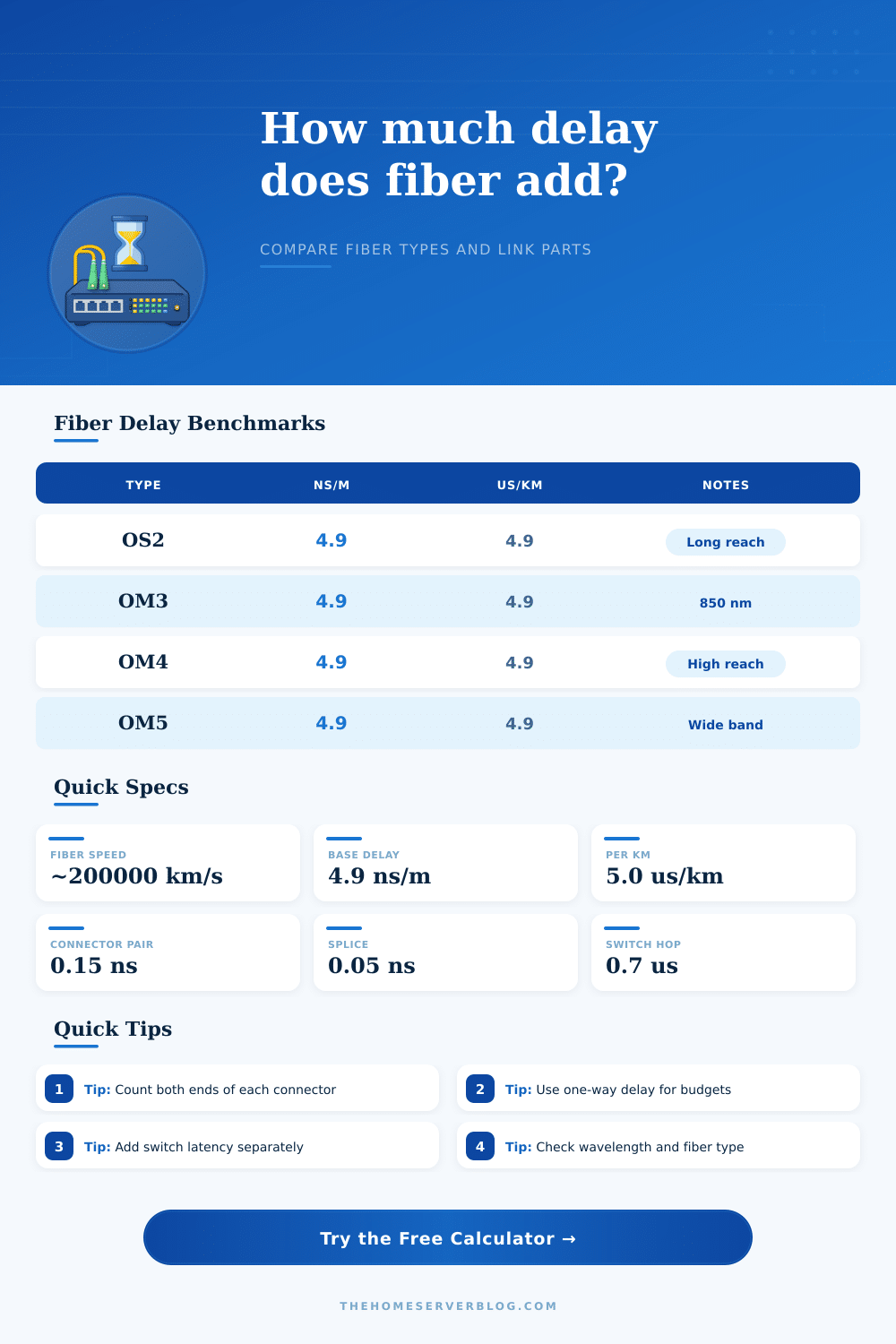
| Fiber Type | Group Index | Delay | Best Use |
|---|---|---|---|
| OS2 single-mode | 1.4672 | 4.893 ns/m | 10 km+ |
| OM3 multimode | 1.4826 | 4.948 ns/m | 300 m |
| OM4 multimode | 1.4827 | 4.949 ns/m | 550 m |
| OM5 wideband | 1.4835 | 4.952 ns/m | 150 m |
| Wavelength | Typical Fiber | Use Case | Note |
|---|---|---|---|
| 850 nm | OM3, OM4, OM5 | Short reach | MMF default |
| 1310 nm | OS2, SMF | General links | Balanced reach |
| 1490 nm | SMF / PON | Access feeder | Often downstream |
| 1550 nm | OS2, SMF | Long reach | Low attenuation |
| Delay Contributor | Model | Added Delay | Comment |
|---|---|---|---|
| Connector pair | Planning allowance | 0.35 ns | Count mated ends |
| Splice point | Planning allowance | 0.12 ns | Usually tiny |
| Transceiver pair | Fixed hardware | 120-260 ns | Depends on optics |
| Switch hop | Fixed hardware | 350-700 ns | Mode matters |
| Scenario | Typical Span | One-Way Target | Notes |
|---|---|---|---|
| Patch lead | Under 20 ft | Under 0.1 us | Mostly optics |
| Floor backbone | 20-200 ft | 0.1-1 us | Keep hops low |
| Campus span | 200 m-2 km | 1-10 us | OS2 preferred |
| PON feeder | 1-20 km | 5-100 us | Splitters add depth |
This calculator keeps optics, glass travel, and active forwarding separate so you can see where latency actually enters the link.
Latency within fiber optic cables are created by light traveling through the fiber, but there are several causes of fiber optic latency. Fiber optic latency isnt just created by the distance of the fiber optic cable. Other factors that creates latency within fiber optic cables include the material of the glass within the fiber, the components within the network, and the connections within the fiber optic network.
Because light does not travel at the same speed through glass as it does through a vacuum, light experiences a delay as it travels through the glass of the fiber optic cable. In single-mode fiber optic cables, light travels at a speed that create a delay of five nanoseconds for every meter of the fiber optic cable. This five nanoseconds delay for every meter of fiber optic cable is one of the major factor to consider when measuring the latency of a long fiber optic cable run.
What Causes Delay in Fiber Optic Cables
The components within the fiber optic network also create latency within the network. The number of mated connectors within the network create latency for the network, as do the number of splices within the network. The number of transceivers within the network, such as QSFP module, also creates latency because of the serialization delays of the fiber optic data.
These serialization delays can be more greater than the delay created by the glass of the fiber optic cable. The fiber optic cables that is purchased have different types of fiber optic cables available. For example, distances that are longer than a few hundred meter use single-mode OS2 fiber optic cables due to the low dispersion of the fiber.
Multimode OM4 fiber optic cables are used for distances between equipment racks that are shorter because they allow the use of lower cost 850nm lasers to transmit data. The wavelength of the data that is sent through the fiber optic network can impact the distance that the signal travels through the fiber before it begin to lose strength. For instance, using a 1550nm wavelength allow the signal to travel the furthest distance through the fiber optic cable with the least amount of loss of that signal.
Using other wavelengths different than the 1550nm wavelength will result in a loss of signal at different rate. If extra lengths of fiber optic cable are to be pulled to cover a specific distance, that extra length of fiber cable must be accounted for in the calculation of the total distance of the fiber optic cable. For instance, if a fiber optic cable is to be pulled a distance of 100 meter, but extra length is required to make bends in the cable, then the length of the fiber that is pulled is 110 meters.
That 110 meters of fiber optic cable must be use to calculate the latency of the network. The addition of active networking equipment can also increase the latency of fiber optic networks. Each time data pass through a network switch, there is an addition of hundreds of nanoseconds of latency to the data.
The type of switching method used by the network switch will impact the latency created by the switch. For example, cut-through switching will add less latency to the network than store and forward switching methods to the network. When using a network, it is helpful to use software that measure the one-way and round-trip latency of the network.
For instance, protocols like iSCSI has a latency requirement for the network, and the total latency of the fiber optic network must be within that requirement. When creating a fiber optic network, a person must manage a latency budget for the network. The network designer can establish the target for one-way latency, and there must be a means of monitoring the margin of latency left for the network.
If the margin for latency is negative, it is necessary to either reduce the number of switches in the network or to replace the optical component within the network. The route length of the fiber optic cable should be calculated according to the actual path that the cable will take through a building. The actual length of the path of the cable will often be longer than the distance calculated on a technical drawing of that route.
Each pair of connectors at each end of a fiber optic cable will add to the total latency of the network, so each pair of connectors must be accounted for in the total calculation of latency. In a network that is small in size, such as a home network, the latency created by the fiber glass is small. However, in a large data center network, the latency of the signal traveling through the glass is of primary concern in the management of the network.