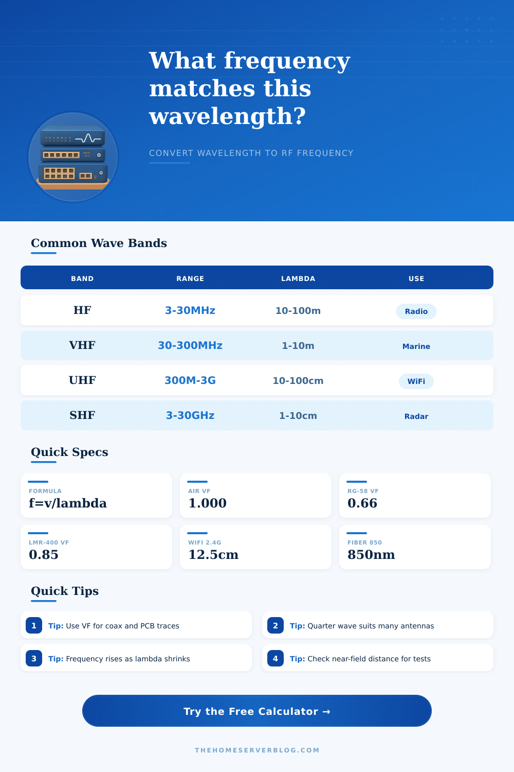
Frequency Calculator for Wavelength
Convert any wavelength into frequency, period, angular frequency, antenna element length, coax delay, and practical RF band using propagation velocity and velocity factor.
Core formula: frequency equals propagation velocity divided by wavelength. Propagation velocity is the speed of light multiplied by velocity factor.
Calculated Wave Results
| Band | Frequency Range | Approx Wavelength | Home Lab Use |
|---|---|---|---|
| HF | 3 MHz to 30 MHz | 100 m to 10 m | Long-wire radio, CB upper edge, amateur radio planning |
| VHF | 30 MHz to 300 MHz | 10 m to 1 m | Weather radio, marine VHF, airband receivers, scanners |
| UHF | 300 MHz to 3 GHz | 1 m to 10 cm | LoRa, cellular, GPS L1, 2.4 GHz Wi-Fi and Zigbee |
| SHF | 3 GHz to 30 GHz | 10 cm to 1 cm | 5 GHz Wi-Fi, 6 GHz Wi-Fi, microwave links, radar modules |
| Optical | Hundreds of THz | 400 nm to 1600 nm | Fiber transceivers, visible LED tests, laser alignment |
| Signal or System | Typical Frequency | Free-Space Wavelength | Useful Element |
|---|---|---|---|
| Wi-Fi 2.4 GHz channel 6 | 2.437 GHz | 12.30 cm | 3.08 cm quarter-wave radiator |
| Wi-Fi 5 GHz channel 100 | 5.500 GHz | 5.45 cm | 1.36 cm quarter-wave radiator |
| Wi-Fi 6E center example | 6.500 GHz | 4.61 cm | 1.15 cm quarter-wave radiator |
| LoRa or ISM sensor node | 915 MHz | 32.76 cm | 8.19 cm quarter-wave radiator |
| GPS L1 receive antenna | 1.57542 GHz | 19.03 cm | 4.76 cm quarter-wave equivalent |
| 850 nm multimode fiber | 352.7 THz in vacuum | 850 nm | Optical wave, not RF antenna-sized |
| Medium or Cable | Typical VF | Delay Per Meter | When to Use It |
|---|---|---|---|
| Air or vacuum | 1.000 | 3.34 ns/m | Antennas, open-air propagation, free-space wavelength |
| RG-58 solid PE coax | 0.66 | 5.05 ns/m | Short bench leads, radio jumpers, older antenna cables |
| RG-6 foam coax | 0.82 | 4.07 ns/m | TV distribution, SDR feeds, receiving antennas |
| LMR-400 foam coax | 0.85 | 3.92 ns/m | Longer low-loss antenna runs and outdoor RF links |
| Cat6 twisted pair | 0.65 | 5.13 ns/m | Ethernet timing estimates and propagation delay checks |
| FR-4 microstrip estimate | 0.55 | 6.07 ns/m | PCB antenna stubs, RF traces, impedance experiments |
| Element Type | Length Formula | Typical Role | Planning Note |
|---|---|---|---|
| Full wave loop | 1.00 x lambda | Loops, resonant perimeter experiments | Often adjusted for conductor diameter and environment |
| Half-wave dipole | 0.50 x lambda | Balanced antennas, basic receiver tests | Each side is about one quarter wavelength |
| Quarter-wave monopole | 0.25 x lambda | Vertical antennas, Wi-Fi-style radiators | Usually needs a ground plane or counterpoise |
| Eighth-wave stub | 0.125 x lambda | Matching experiments and compact layouts | Strongly affected by line VF and nearby materials |
| Electrical coax length | lambda x fraction x VF | Phasing harnesses, delay lines, stubs | Use cable datasheet velocity factor when available |
The velocity factor are the decimal value that defines how fast the electromagnetic waves travels through a specific medium compared to the speed of light. People often believe that the speed of light is a constant and will never vary from its set speed. However, the speed of light is only constant when the speed of light are traveling through a vacuum.
When an electromagnetic wave travel through a material, such as a fiberglass circuit board or a coaxial cable, the electromagnetic wave will travel at a slower rate. Consequently, the length of the electromagnetic wave through the material will be more shorter than the length of the electromagnetic wave that is traveling through a vacuum. If an antenna is design with the length of an electromagnetic wave traveling through a vacuum but built with a material that has a velocity factor for that material, then the antenna will be tuned to the wrong frequency.
Velocity Factor: How Wave Speed Affects Antenna Length and Cable Delay
The velocity factor will tell an engineer the speed of the electromagnetic wave relative to the speed of light. For instance, if the velocity factor of a coaxial cable is 0.66, then the electromagnetic wave is traveling at 66% the speed of light. Because the velocity factor of a material will always reduce the speed of the electromagnetic wave traveling through that material, the velocity factor will also reduce the length of the electromagnetic wave that is traveling through the material.
If an engineer dont account for the velocity factor when calculating the physical length of an antenna, then the antenna will not function correct. Thus, you must use the velocity factor to calculate the physical length of an antenna that will function correctly. The wavelength calculator will define the physical length of one full cycle of an electromagnetic wave.
However, antennas do not use the full wavelength of the electromagnetic wave. Instead, antennas use fractions of that wavelength. For instance, many antennas use fractions of wavelengths such as quarter wave monopoles or half wave dipoles because these fractions of wavelengths will resonate with the electromagnetic wave and allow it to efficiently travel into the air as a signal.
The calculator allows you to choose whether your measurement is for the number of full wavelengths or fractions of wavelengths. Depending on this value, the calculator can provide you with the correct length for your antenna. The frequency of the signal will determine both the size of the antenna and the wavelength of that radio signal.
The higher the frequency, the shorter the wavelength. The HF band have wavelengths that are very long, meaning the antennas must be very long to effectively transmit these signals. In contrast, the UHF and SHF bands have wavelengths that are very short, meaning the antennas for these frequencies will also be very short.
Because these antennas are short in length, the physical components of the antennas is critical. A small piece of solder or metal casing can act as a parasitic element of the antenna. This parasitic element can cause shifts in the frequency of the signal from the antenna, which may cause the connection between the antenna and the receiving device to fail.
The signal will contain a range of frequencies. The range of these frequencies is called the bandwidth of the signal. The wavelength of the signal at the bottom of the bandwidth will have a different length different than the wavelength at the top of the bandwidth.
If the antenna is only tuned to a narrow range of frequencies within the signal, the antenna may not effectively receive the entire signal. To combat this, you must consider the edges of the bandwidth of the signal to determine whether your antenna will need a wider buffer to effectively receive the signal. The speed at which the electromagnetic wave travels will have an impact on the run delay of the signal.
The run delay is the amount of time that it take for the signal to travel from one point to another on the communication medium. Because the electromagnetic wave will travel at a slower rate within the cable than within the air, using very long communication cables will result in a lag in the signal. This lag in the signal is referred to as the run delay.
This run delay can cause shifts in phase of the signal in the laboratory. If you know the number of nanoseconds of delay per meter of communication cable, you can compensate for the length of the communication cable. By compensating for the length of the communication cable, you can trust the readings of the oscilloscope.