Horn Antenna Gain Calculator
Estimate gain, beamwidth, and aperture efficiency for RF horn designs used in home labs, benches, and microwave links.
Full Breakdown
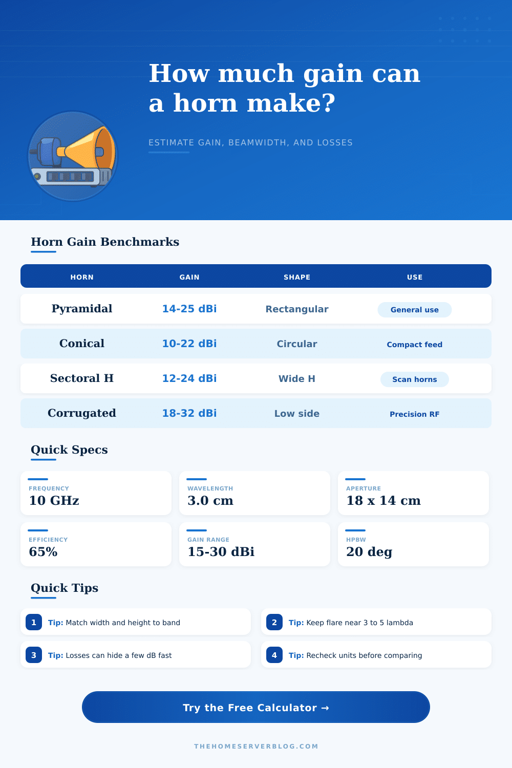
| Horn family | Aperture shape | Typical gain | Best fit |
|---|---|---|---|
| Pyramidal | Rectangle | 14-25 dBi | General RF work |
| Sectoral H | Rectangle | 12-22 dBi | Wide scan sectors |
| Sectoral E | Rectangle | 12-22 dBi | Shaped vertical beam |
| Conical | Circle | 10-22 dBi | Round feed patterns |
| Band | Wavelength | Common horn | Check |
|---|---|---|---|
| 2.4 GHz | 12.5 cm | Pyramidal | Wi-Fi and ISM |
| 5.8 GHz | 5.2 cm | Small feed horn | Short bridge links |
| 10 GHz | 3.0 cm | Sectoral | Ham and radar |
| 24 GHz | 1.25 cm | Corrugated | Sensor horns |
| Quantity | Equation | Units | Meaning |
|---|---|---|---|
| Wavelength | lambda = c / f | m | Shorter at high band |
| Aperture area | A = w x h | m^2 | Starts the gain math |
| Gain | G = 4 pi Aeff / lambda^2 | linear | Convert to dBi |
| Beamwidth | HPBW = k lambda / d | deg | Each axis differs |
| Check | Good range | If low | If high |
|---|---|---|---|
| Width/height ratio | 1 to 4 | Pattern stays broad | Beam gets very thin |
| Flare length | 3 to 5 lambda | More phase error | Build gets bulky |
| Efficiency | 55% to 85% | Waste and spillover | Hard to hold in real builds |
| Far field | 2D^2 / lambda | Near field readings | Use for clean test distance |
This calculator keeps aperture size, frequency, and practical loss separate so you can compare horn families without mixing in unrelated RF assumptions.
A horn antenna is a device that focuses the radio waves into a beam. The horn antenna use its flared shape to capture the energy that radiates from an aperture of the antenna. The aperture areas of the antenna and the wavelength of the signal radiated from it determine the gain of a horn antenna.
Therefore, the dimensions of a horn antenna must be balanced to obtain the desired gain from the antenna. If the aperture area of a horn antenna are too small, the efficiency of a horn antenna will decrease due to spillover. However, if the aperture area of a horn antenna is too large, the antenna will develop phase errors in the radio signal, reducing the quality of the signal radiated from the antenna.
How a Horn Antenna Works and How to Design It
There is various types of horn antennas that are used for specific purposes. Pyramidal horn antennas are used because they are rectangular in shape and split the radio beam evenly between the two planes. Sectoral horn antennas are used for specific applications where one dimension of the horn antenna is stretched out more far than the others.
Conical horn antennas use a circular shape for the antenna. A horn antenna must have a flare length that is long enough to even out the electromagnetic field radiating from the antenna. For instanse, a flare length of three to five wavelengths are used to even out the radio waves and avoid quadratic phase error that can occur in the antenna.
The efficiency of a horn antenna will never reach the theoretical maximum. Feed losses will occur in the antenna during the transmission of the signal from the horn antenna. Feed losses can happen due to impedance mismatches between the antenna and the horn or tapers in the horn antenna.
Due to feed losses, horn antennas will have an efficiency of between 60% to 80%. The wavelength of the radio signal radiated from the horn antenna will dictate the physical size of the horn antenna. As the frequency of the signal increase, the wavelength of the signal will decrease.
Thus, a smaller wavelength will result in a smaller horn antenna. The area of the aperture of a horn antenna will have a relationship with the beamwidth of the antenna. As the area of the aperture of a horn antenna is increased, the gain of the horn antenna will increase.
However, as the aperture area of a horn antenna is increased, the beamwidth will narrow. A narrower beamwidth means that the horn antenna has a smaller coverage area. If the horn antenna have a beamwidth that is too narrow, it will emit sidelobes that can reduce the quality of the link budget of the antenna.
However, if corrugated walls are used in the horn antenna, the corrugated walls will reduce the emission of sidelobes. Corrugated walls choke the stray radio signals that radiates from the horn antenna. For best results, a horn antenna should of been tested in the far field.
The distance from the horn antenna to the far field can be calculated with the formula of twice the aperture wavelength divide by the wavelength of the signal radiated by the antenna. Using this formula will allow people to trust the measurement of the horn antenna. By maintaining the correct geometry for the horn antenna and balancing the aperture dimensions of the antenna with the length of the flare of the horn antenna, the horn antenna will focus the radio waves into a beam to effectively radiate the signal for various applications.