LoRa Spreading Factor Calculator
Compare LoRa spreading factor, bandwidth, coding rate, payload size, preamble, link budget, noise floor, target SNR, gateway distance, and duty cycle before choosing a radio profile for sensors, meters, trackers, and home lab gateways.
Time occupied by one LoRa chirp symbol.
Payload and coding symbols after header, CRC, and FEC.
Maximum packet count allowed by the chosen duty cycle.
Modeled path budget at the selected gateway distance.
| Spreading factor | Chips per symbol | Demodulator SNR | Planning behavior |
|---|---|---|---|
| SF7 | 128 | -7.5 dB | Fastest common LoRaWAN profile; best for nearby gateways and frequent packets. |
| SF8 | 256 | -10 dB | Good first step when SF7 margin is thin but airtime still matters. |
| SF9 | 512 | -12.5 dB | Balanced range profile for garden sensors, meters, and light obstructions. |
| SF10 | 1024 | -15 dB | Longer edge coverage with a clear airtime penalty. |
| SF11 | 2048 | -17.5 dB | Slow but useful for weak paths, underground meters, or sleepy devices. |
| SF12 | 4096 | -20 dB | Maximum spreading and longest airtime; use sparingly on shared channels. |
| Bandwidth | Range effect | Data-rate effect | Common use |
|---|---|---|---|
| 7.8-31.25 kHz | Highest sensitivity | Very low throughput | Private links where narrow channels and long packets are acceptable. |
| 62.5 kHz | Better than 125 kHz | Half the symbol rate of 125 kHz | Special long-range links with careful channel planning. |
| 125 kHz | Standard LoRaWAN balance | Baseline data rate | Most EU868, US915, and home lab LoRaWAN uplinks. |
| 250 kHz | Lower sensitivity | Roughly double 125 kHz | Shorter links, faster packets, and some regional downlink profiles. |
| 500 kHz | Lowest sensitivity | Roughly four times 125 kHz | High-rate bursts and short-range lab testing. |
| Coding rate | Overhead ratio | Relative airtime | When to use |
|---|---|---|---|
| 4/5 | 1.25x | Lowest | Default choice when packet loss is already acceptable. |
| 4/6 | 1.50x | Moderate | Useful for slightly noisy paths without jumping SF. |
| 4/7 | 1.75x | High | Extra FEC for difficult private links and repeated fades. |
| 4/8 | 2.00x | Highest | Maximum coding overhead; compare against raising SF first. |
| Duty cycle | Airtime per hour | Planning impact | Practical note |
|---|---|---|---|
| 0.1% | 3.6 seconds | Very tight | Reserve for rare alarms or very short payloads. |
| 1% | 36 seconds | Common cap | SF11 and SF12 packets can consume this quickly. |
| 10% | 6 minutes | Private lab friendly | Still watch collisions if many nodes share one channel. |
| 100% | Unlimited model | No duty cap | Regulations, fair access, and gateway capacity may still limit use. |
It’s just an idea, but one so simple: Every few hours, a small packet of data about soil moisture in the back yard arrives at a gateway on the porch. Seem trivial? This seems trivial until you consider that same radio chip could have whispered three miles over a thick oak forest to tell you what was going on in the mailbox sensor.
That’s not a hardware problem. That’s a spreading factor problem. It is a setting that determines how much a signal spreads across the spectrum to overcome distance and interference. Get it right and your network hums along for years, get it wrong and your packets never arrive, your battery drains, or your airtime vanishes.
How to Choose the Right Settings for Your Signal
That math can be done by hand, but who wants to guess between SF7 and crawling all the way up to SF12? With our calculator, you just plug in distance and your link budget and let math do its thing.
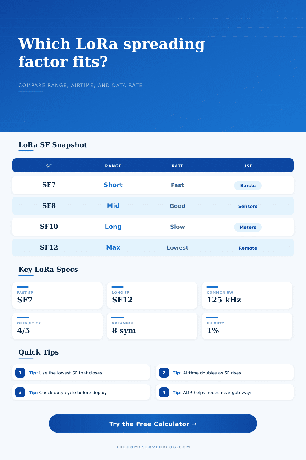
If you think about trade-off between speed and spreading factor, the faster the speed is, the less distance you will get. So if you set spreading factor to SF7, you get a fast (tight) signal. You get lots of data rates but short airtime. And you have to has a good signal-to-noise ratio on the receiving end.
This is good when the gateway is close and there isn’t much stuff in the way off the path. Push SF7 thru thick foliage or brick walls and link is toast.
Increase the spreading factor to say SF9 or SF10. Now you slow things down. You transmit slower and the data rate goes down, but now your receiver gets more sensitive. It can pulls valid data out of what looks like static at lower settings. This makes it possible to get signal to travel farther. It can go over longer distances and through more obstructions.
The cost is time. Every packet takes up channel longer. In a shared network, that matters. When you use a higher spreading factor, you’re borrowing time from your neighbor each time you do so.
So what happens when we change the bandwidth? The bandwidth setting works in opposition to the spreading factor. The higher the bandwidth (e.g., 500 kHz), the more data you can send. However, that also increases noise floor. In other words, it’s hard to talk over someone in a noisy room.
Conversely, a lower bandwidth (e.g., 125 kHz) is quieter. It decreases the noise floor and makes things more sensitive but limits how much data you can push through. This is why most LoRaWAN deployments stick to 125 kHz. Sensitivity and speed tend to balance out when dealing with normal sensor payloads.
For example, if you’re simply sending small packets every few minutes from a meter attached to a battery, using 250 kHz won’t necessarily give you any more speed. All that does is eat away at your sensitivity. You don’t want your signal to be faster than the noise; you want it to be louder than the noise.
And then there’s the other, quieter variable: Coding rate (the amount of redundancy added to your data). The more efficient ones are like 4/5, which assumes a clean channel. So if your leaves get wet in the rain and cause signal to fade, that efficiency turns into fragility. Increasing your coding from 4/5 to something like 4/6 or 4/7 adds additional symbols that the receiver can use to fix errors.
This doesn’t impact the spreading factor, but it does increases the airtime. It’s a subtle dial to make link more robust. Something you’d do if the link was borderline but you don’t want to pay the hefty penalty of jumping to the next spreading factor.
The hard constraint is duty cycle. Typically, in most areas, it’s 1% airtime. Sounds good, but what does that mean? With an SF12 or higher coding rate, it take seconds to send large amounts of data. It may mean that you’re only able to send a few packets an hour.
The calculator will tell you precisely how many packets you have room for in your budget. Too small and you’ve got a design problem. Try a shorter preamble, try smaller payloads, move closer to the gateway.
The planner in the real world didn’t do that. They went with SF12 just to make sure all their packet were received. They also forgot about the airtime tax. Gateway floods, more collisions, and dead batteries occur. You want to keep the channel open for you and everybody else. And save some energy too.
Close the link with the lowest spreading factor. Here’s where math table on the page makes it clear… There’s no free lunch here. You gain sensitivity but lose speed.
Keep it simple. Test the margins. Only change if you need to. That’s the discipline that transforms a prototype into something useful.