MPO Fiber Polarity Calculator
Map MPO Type A, Type B, and Type C trunks across cassettes, key orientation, gender, parallel optics, duplex breakouts, and field test margin before patching a dense fiber link.
MPO polarity result
| Polarity type | End A to End B map | Typical use | Calculator treatment |
|---|---|---|---|
| Type A | 1 to 1, 2 to 2, through the array | Cassette links and Method A designs | Straight mapping, then cassette and patch rules are applied. |
| Type B | 1 to 12, 2 to 11 on MPO-12 | Parallel optic direct links and Method B | Full reversal across the selected fiber count. |
| Type C | 1 to 2, 2 to 1, pair by pair | Duplex trunk polarity management | Adjacent fibers are swapped before other path effects. |
| Universal | Module-dependent | Vendor-managed cassette systems | Scores labels and cassette count higher than raw cable label. |
| Fiber count | Parallel optic pattern | Duplex breakout capacity | Common validation point |
|---|---|---|---|
| MPO-8 | 4 Tx and 4 Rx lanes | 4 duplex ports | Confirm no installer assumes MPO-12 center fibers. |
| MPO-12 | 4 Tx, 4 Rx, often 4 dark center fibers | 6 duplex ports | SR4 usually uses outer four positions on each side. |
| MPO-16 | 8 Tx and 8 Rx lanes | 8 duplex ports | Verify vendor lane order at both transceivers. |
| MPO-24 | 12 Tx and 12 Rx lanes or two MPO-12 groups | 12 duplex ports | Check group A/B cassette orientation and labels. |
| Polarity method | Trunk expectation | Patch expectation | Risk if mixed |
|---|---|---|---|
| TIA Method A | Type A trunk through aligned adapters | One A-to-B duplex patch cord in the channel | Two same-ended duplex patches can leave Tx facing Tx. |
| TIA Method B | Type B trunk or equivalent reversal | Same orientation patches at both ends | Extra cassette flip can reverse the lane order again. |
| TIA Method C | Type C pair-flip trunk | Mostly duplex distribution | Parallel optics may see scrambled lane groups. |
| Parallel SR/DR | Usually Type B direct MPO path | MPO patching without LC cassette swaps | Wrong keying can make all lanes land on the wrong side. |
| Validation item | Good sign | Warning sign | Calculator score effect |
|---|---|---|---|
| Gender and pins | One connector pinned, one unpinned | Both pinned or both unpinned | Large penalty because the link may not mate safely. |
| Key orientation | Matches the method drawing | Unknown adapter or unexpected key-up/key-up face | Reduces confidence and may apply a reversal. |
| Breakout labels | Fiber positions and LC ports are documented | Only port numbers or no labels | Lower score because field tracing is required. |
| Measured margin | Worst lane has positive dB headroom | Any active lane has negative margin | Directly drives pass, tight, or fail validation state. |
It’s deadline time. You’re in a server room surrounded by boxes full of MPO cabling. There is a patch panel that appears to have been installed during the last upgrade cycle, and no one bothered to document it. Plug that cable in incorrectly and your 40G links turns dark.
That’s what polarity is all about and why so many folks don’t talk about it enough. Yes, light needs to get from point A to point B. It also needs to make sure the transmitter on one side communicate with the receiver on the other. The calculator above manages the mapping logic for you. However, having some idea of why it matters keeps you from blindly using the tool when hardware resists.
What Is MPO Polarity?
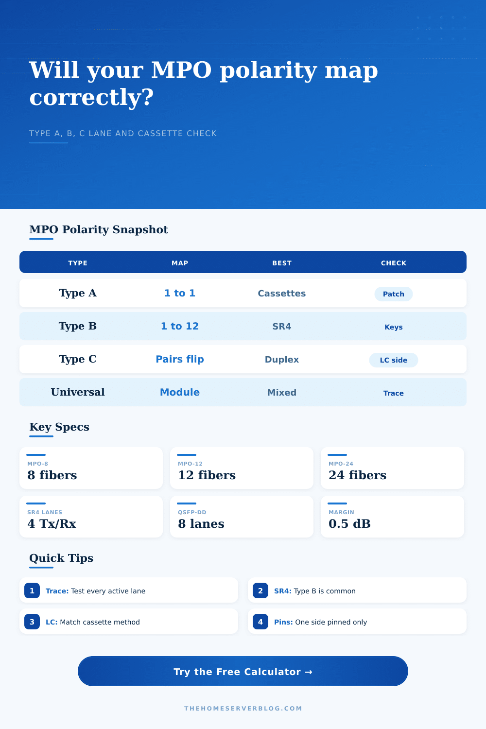
Fiber has directionality. If the physical path of a fiber strand gets reversed somewhere in its journey, you can’t send some data down it and have it come out at proper destination. Three primary methods address this problem:
Type A preserves fiber order. This sounds easy enough until you try sending or receiving data between two piece of equipment with reversed pinouts that require a reversal.
Type B reverses all of the fibers. This is standard with parallel optics such as SR4, as it lines up first fiber on the plug with the last one on the receptacle.
Type C flips adjacent pairs. This is great when used in duplex applications where only certain lanes needs to be flipped but not the entire bundle.
This is perhaps the most common rookie mistake: choosing the wrong type for your link setup. Making matters more complicated are cassettes, each one adds another flip point. Depending on how cables are run into the module, every time it goes through a cassette there’s the potential that the position of the fibers could change. That’s where you can use the calculator by entering the orientation of the trunk and number of cassettes.
Why does it matter? Because having an odd number of cassette flips can cause the whole link to be reversed in polarity. Two cassettes in line will cancel each other out, three won’t. Know your chain.
Keep lanes strictly aligned. With parallel optics such as QSFP+ modules, the lanes must align exactly. A 4-lane transceiver has certain specific fibers reserved for receive and transmit. If the lane polarity isn’t right, then what lane one sends from sender arrives at lane four on the receiver. It may light up but it won’t perform well if at all. The tool maps out those positions so that you can visually verify which lane one is connected to lane one. It saves hours of troubleshooting. Wouldn’t you rather know about your lane mismatch before you terminate forty eight fibers?
Now we get to pins and gender. Pinning is always forgotten until it doesn’t work anymore, but it is just as important. You can only connect an MPO connector to another MPO connector where one is pinned and the other isn’t. Plug a pinned into a plugged, and you’ll damage the ferrule. That’s checked by the calculator so you don’t try to force two things that won’t mate. This is also a physical constraint on how the cable is put together. Do you have any mixed-gender cables in your inventory? Carefully trace out the path based off of it.
Test margin provides a reality check on the optical performance. The polarity may be right but a tight bend or a dirty connector will still kill it. Running in your measured margin proves that the link works. As long as the polarity map appears perfect, then a negative margin indicate the link is failing. This connects how it’s installed to how it actualy works.
Labeling standards are important for long term upkeep. Document how the fibers are positioned and what way their polarity is facing. Otherwise, the following tech will guess. And guess wrong. Guess wrong = breaks stuff. A little habit like printing a lane map and sticking it inside the patch panel door pays big benefits during outages. The calculator generates this for you… But only if you keep it handy.
All-in-all, MPO polarity is a matter of figuring out a logic puzzle where all the pieces need to fit together. It’s a puzzle that gets solved by the calculator, as long as you give it the right information. Make sure you know what gender you are. Count how many cassettes there are. Check the margins on each end. Double-check your cable type(s). And then stick the cable into place, confident that light will go where it should.