HomeServerBlog rack cabling planner
Rack Cable Manager Capacity Calculator
Estimate usable cable-manager cross-section, fill percentage, remaining cable count, bend-radius clearance, bundle density, and patch-cord slack load for horizontal and vertical rack managers.
1Rack cabling presets
2Manager, cable, slack, and bundle inputs
Capacity breakdown
Bundle and bend details
3Live fill, remaining, bend, and bundle cards
After type factor, fill target, spare reserve, and slack allowance.
Round cable cross-section multiplied by the cable count.
Uses bundle count, cable OD, and packing efficiency.
Similar cables left while keeping the spare reserve intact.
4Manager type comparison grid
5Cable manager capacity tables
Common rack manager openings
| Manager opening | Gross area | Practical fill | Typical rack use |
|---|---|---|---|
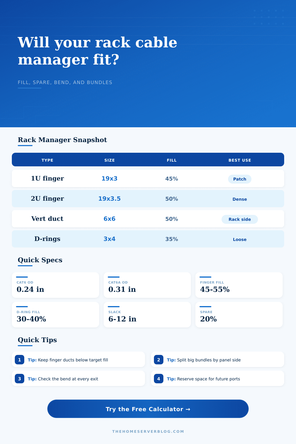
| 1U x 3 in duct | 57 sq in | 45% to 55% | Front patch panel rows and switch uplinks. |
| 2U x 3.5 in duct | 66.5 sq in | 50% to 60% | Dense copper patch cords and longer service loops. |
| 4 in x 6 in vertical | 24 sq in | 45% to 55% | Rack-side distribution between equipment groups. |
| 6 in x 6 in vertical | 36 sq in | 45% to 55% | High-density side routing in a full-height rack. |
| 3 in D-ring depth | 12 to 18 sq in | 30% to 40% | Loose rear routing, short side jumps, and service access. |
Cable OD and bend reference
| Cable mix | Typical OD | Bend planning | Manager note |
|---|---|---|---|
| Slim patch | 0.15 to 0.18 in | 4x OD | High count but avoid sharp exits at switch ports. |
| Cat6 patch | 0.22 to 0.26 in | 4x OD | Good default for home lab copper patches. |
| Cat6A patch | 0.29 to 0.34 in | 4.5x OD | Needs deeper managers and looser bundle groups. |
| Fiber patch | 2.0 to 3.0 mm | 10x OD | Small area, but bend radius usually controls layout. |
| DAC twinax | 0.20 to 0.30 in | 5x OD | Stiffer cable can crowd the rear of the rack. |
Bundle planning bands
| Fill band | Manager feel | Recommended action | Risk signal |
|---|---|---|---|
| Under 35% | Open and easy to service | Keep spare visible and label cable groups. | Usually low risk. |
| 35% to 55% | Normal planned density | Good target for finger duct and vertical managers. | Watch bend exits. |
| 55% to 75% | Tight but workable | Split bundles or move slack outside the duct. | Covers may press cable. |
| Over 75% | Hard to modify | Use larger duct, second manager, or fewer service loops. | Recabling becomes slow. |
Preset scenario map
| Scenario | Cables | Manager type | Why it matters |
|---|---|---|---|
| 1U Patch Panel | 24 Cat6 | 1U finger duct | Baseline front patch manager with modest slack. |
| Cat6A Dense Rack | 96 Cat6A | 2U finger duct | Thicker cable quickly consumes bend and fill room. |
| Vertical Side Duct | 144 Cat6 | Vertical finger duct | Side channels carry many small bundle groups. |
| Fiber Patch Shelf | 72 fiber | Horizontal D-ring | Area is small, but radius is the real constraint. |
| Mixed AV and LAN | 60 mixed | Waterfall manager | Mixed diameters lower packing efficiency. |
6Rack cable manager tips
This calculator is a planning aid for rack cable management. Confirm cable manufacturer bend limits, rack hardware dimensions, airflow needs, firestopping, and local low-voltage installation requirements before final routing.
It starts off perfectly: a blank new rack with all the servers lined up just so, the fans whirring silently, and everything looking spiffy from the front. And then you crack it open to plug in that single cable. Before you know it, what were neat rows of patch cables has become an unholy tangle.
This is a typical failure point for data center construction, because no one designs for volume until they are out of space. It’s not the cable. Typically it’s distance between the devices. People think they’ll just stick something in a 19-inch rack. That works until it doesn’t. What looks like inches of width on the outside of a cable manager isn’t what you get on the inside. There are walls, there is exit points and there are covers to those finger ducts.
Why Cable Management Fails and How to Fix It
And when everything is packed in too closely, it causes friction. That means no easy changes in the future. It slow equipment over time as well and creates heat traps.
The solution is to think about the percentage of fill instead of the number of cords. That’s what the calculator does to turn your combination of cables into some form of useful metric (area). Why? Because not all cables are created equal. A Cat6 doesn’t take up as much room than a Cat6A. You can’t just switch out one for the other and expect everything to fit. It’ll blow past. By allowing you to choose your cable category, the calculator automaticly fills in the outside diameters so that it factors in whether you’re using Cat6 or Cat6A.
One big threat to rack integrity is the bend radius. Copper cables are flexible, but they’re not infinitely so. Bending a copper cable too tightly will introduces loss and degrade signal quality. Fiber is even more sensitive to it. To prevent this, the calculator checks bend clearances. It ensures that manager depth is enough. If there’s a conflict, it mean you’re forcing cables into shapes they weren’t designed for. This can eventualy lead to breaking internal conductor or cracking fiber cladding. Unfortunately this problem is hard to diagnose until your network starts dropping packets.
There’s also one more factor that makes planning tricky: Slack. You need extra length so you can remove and replace a cable without having to fully disconnect it. But if you store loops of slack in a shallow finger duct, then you’re wasting space: increasing the bundle’s cross sectional area without any gain in connective capability. Better to route your excess behind the rack (or in an isolated vertical channel). To help you see the trade-off, tool shows difference between the slack load and the area occupied by cables already installed.
There are human factors too. Some day you’re going to want to upgrade a port or add a switch and you’ll have to do something else. At 90 percent fill, everything is a big project. You’ve got five cables you should of undone just to get to the one you wanted. A nice 20 percent or so reserve is a spare area for maneuvering, which sounds wasteful but is an investment in how easy the setup will be down the road. Note the figure on the page showing typical fill bands for different kinds of managers; what it says is that structured finger ducts don’t approach congestion nearly as fast as some other system (such as loose D-rings).
Be patient. It is physics. Cable management is not magic. The plastic channels you purchase has a finite volume. Understanding the relationship of diameter, bend radius, and fill percentage removes guesswork and replaces it with engineering. You create a rack that looks good now and is easy to work with in the future. Don’t just try to squeeze as many cables into place. Fit the right cables with room to breathe.