OSPF Dead Interval Calculator
Estimate OSPF adjacency failure detection, reroute timing, hello load, and BFD speedup for real LAN, WAN, NBMA, DMVPN, and home lab routing designs.
Full OSPF Adjacency Breakdown
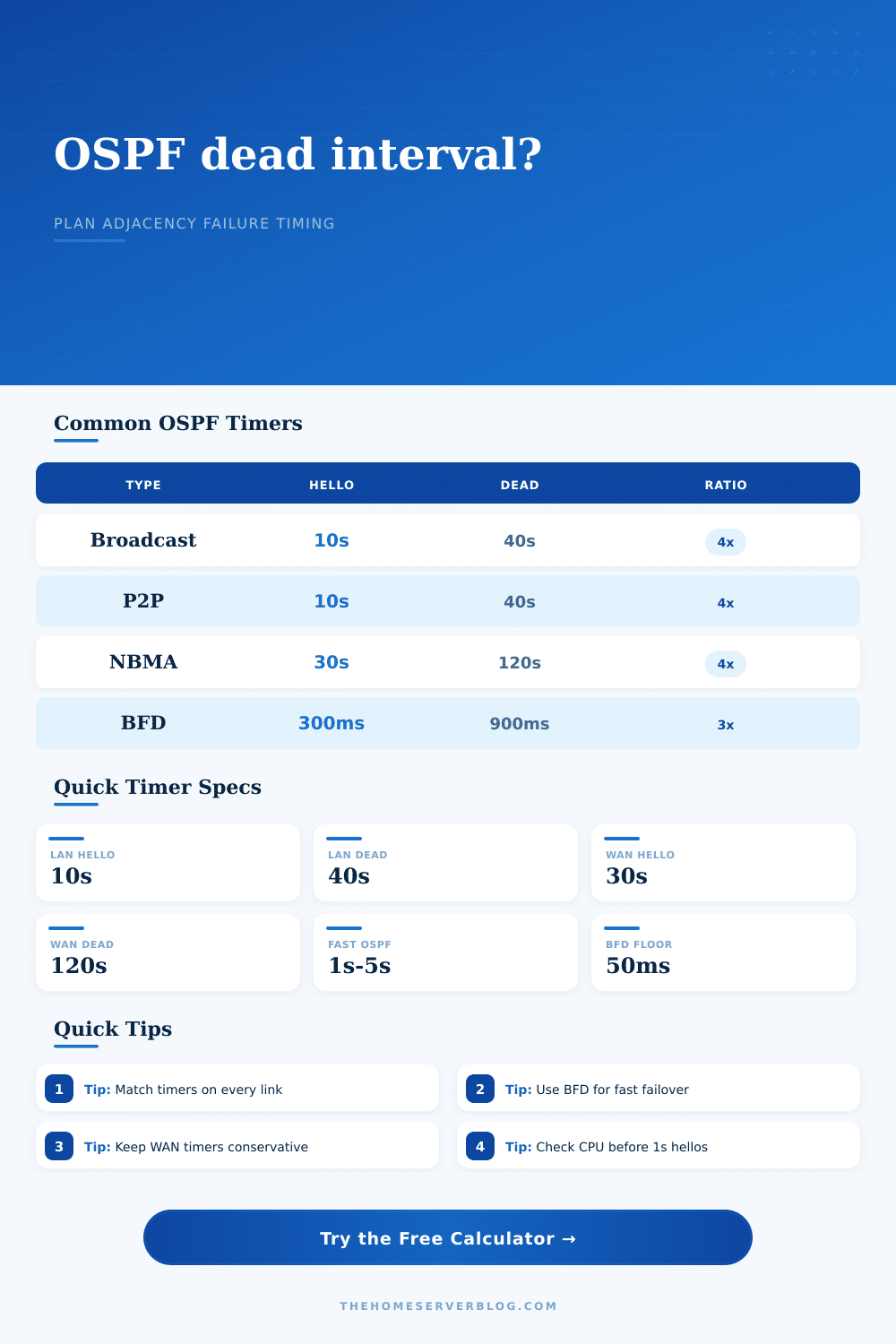
| OSPF Network Type | Typical Hello | Typical Dead | Use Case |
|---|---|---|---|
| Broadcast / Ethernet | 10 seconds | 40 seconds | Switch VLANs, routed SVIs, shared LAN segments |
| Point-to-point | 10 seconds | 40 seconds | Fiber, routed uplinks, lab router-to-router links |
| Point-to-multipoint | 30 seconds | 120 seconds | Hub-and-spoke designs without broadcast emulation |
| NBMA | 30 seconds | 120 seconds | Legacy Frame Relay, some tunnel clouds, manually mapped neighbors |
| Virtual link | 10 seconds | 40 seconds | Temporary backbone repair between ABRs |
| Timer Profile | Formula | Detection Range | Operational Fit |
|---|---|---|---|
| Default LAN | 10s hello × 4 | About 40 seconds | Stable, low CPU impact, slower failure declaration |
| Conservative WAN | 30s hello × 4 | About 120 seconds | Useful when jitter and packet loss are normal |
| Fast OSPF | 1s hello × 3 or 4 | About 3 to 4 seconds | Can work on clean links but raises control-plane load |
| Graceful Core | 5s hello × 4 | About 20 seconds | Middle ground for small routed cores and labs |
| Sub-second Assist | BFD detects, OSPF reacts | About 150 to 900 ms | Best for fast failover when platform support is solid |
| Scenario | Suggested Hello | Suggested Dead | Watch Closely |
|---|---|---|---|
| Home lab routed core | 5 to 10 seconds | 20 to 40 seconds | Small router CPU during image backups or VM storms |
| Campus access ring | 5 seconds | 20 seconds | Loop-free alternate coverage and SPF throttling |
| DMVPN or tunnel hub | 10 to 30 seconds | 40 to 120 seconds | Packet reordering, crypto CPU, spoke count |
| Lossy wireless bridge | 20 to 30 seconds | 80 to 120 seconds | Rain fade, channel changes, queue spikes |
| Data center core with BFD | 10 seconds | 40 seconds | BFD session stability and hardware offload support |
| Detection Method | Typical Timer | Strength | Tradeoff |
|---|---|---|---|
| OSPF default dead interval | 40s LAN / 120s NBMA | Simple and broadly compatible | Slow for voice, storage, and fast-reroute paths |
| Fast OSPF hello/dead | 1s to 5s hello | Improves detection without another protocol | More hello packets and higher false-down sensitivity |
| BFD conservative | 900ms to 1500ms | Fast enough for many routed home labs | Requires BFD support and tuning on both ends |
| BFD aggressive | 150ms to 300ms | Very fast failure signaling to OSPF | Can flap on virtualized routers or busy CPUs |
Timer changes must be applied consistently on both OSPF neighbors. A hello/dead mismatch prevents the adjacency from forming.
This leads to the OSPF dead interval trap: Network reality hits your timing assumptions. You have a link that is down, but there is no packet loss. The adjacency are down. But it’s not a configuration syntax error, nor a hardware failure. It’s a calculation of how long you wait before declaring a neighbor dead.
That depends on factors like link type, CPU load, and even jitter. The calculator help you run the math on how those factors will impact that declaration. A hello packet serves as proof of life because OSPF sends them. No hello packets for the dead interval, and boom! The neighbor is gone from your table.
How to Set OSPF Timers Correctly
By default, this is set as four times the hello interval. In other words, on a typical Ethernet link, we wait forty seconds before it time out. Forty seconds seems like a reasonable amount of time. It’s safe. It’s stable. But in today’s latency sensitive (voice) network or data center, forty seconds might be an eternity.
Know what you’re measuring. You’re not just counting packets. You’re counting tolerance. What it does take into account are things that pure theory doesn’t consider. It include control-plane busy delays and observed hello jitter. Routers don’t live in a vacuum. When there’s a route convergence event, the router may stop its hello processing for a few hundred milliseconds while the CPU catch up. That pause appears as if the router has failed. You’ll see flapping adjacencies where none exist.
The calculator increase the base dead interval by adding the jitter and CPU overhead time. This gives you a realistic failure detection window different than an idealized one. A lot of folks think fast but forget stable. Finally, take into account the type of link: Broadcast Ethernet behaves different than a noisy wireless bridge or a DMVPN tunnel. Decrease your timers on a clean fiber link so you can fail over quick. Do the same thing on a lossy microwave link and you’ll have constant churn. Note that the reference tables explains why NBMA links default with a 30 second hello interval and a 2 minute dead interval. That’s about appropriateness, not speed.
It’s fast, and it costs something. A timer that is aggressive creates hello packets. Hello packets translate into extra CPU cycles used doing things other than forwarding packets. Have two dozen interfaces all running OSPF? If you cut the hello interval from ten seconds to one second, you’ve got a tenfold increase in control-plane workload. That’s the packet-per-minute impact of your choices as estimated by the calculator. You get speed at the expense off resources. You seldom get both (without other mechanisms).
One solution comes with Bidirectional Forwarding Detection (BFD). In its simplest form, BFD is a lightweight heartbeat independent of the routing protocol. While OSPF has slow, safe timers, BFD can detects failure in sub-second intervals. The calculator shows BFD assist modes. You enter an aggressive or conservative BFD profile, then it calculates the resulting effective detection time. The ability to separate these features are powerful. Now you can achieve both protocol stability (via OSPF) and fast detection (via BFD).
So what do you do with that? Look at the reroute ready estimate, which includes the SPF calculation time plus the time for FIB installation. Remember, it’s only half the battle to detect a failure: the router must then recompute the best path and rebuild its forwarding table. That doesn’t happen instantly… It takes time in a large topology. It doesn’t matter how quickly you detected a failure if it take five seconds to install the new route. That’s where the safety buffer input comes into play, so you can account for those downstream times.
Tuning timers is a test of confidence. It tests your confidence in your hardware and your links. It also tests your ability to cope with temporary failures and still keep ticking along. Stick with defaults. Take measurements for CPU and jitter and what realy happens. Tweak. Don’t go after some theoretical ideal. Go after something that actualy works reliably. When you’re pushing things too far, they’ll let you know. Believe them. Next time the storms come, your network will work better.