HomeServerBlog rack power planner
PDU Breaker Derating Calculator
Estimate usable PDU breaker amps and watts after continuous-load rules, ambient temperature, phase mode, power factor, redundancy failover, connected load, and target headroom.
▦Breaker presets
⚙PDU breaker inputs
Derating breakdown
Capacity and feed check
📊Live capacity cards
Breaker amps before derating, power factor, or redundancy.
NEC-style adjustment from the entered ambient temperature.
How much each surviving breaker must carry in the selected redundancy mode.
Capacity after derating, redundancy, and requested headroom.
🔎Circuit comparison grid
📐Breaker and NEC-style reference tables
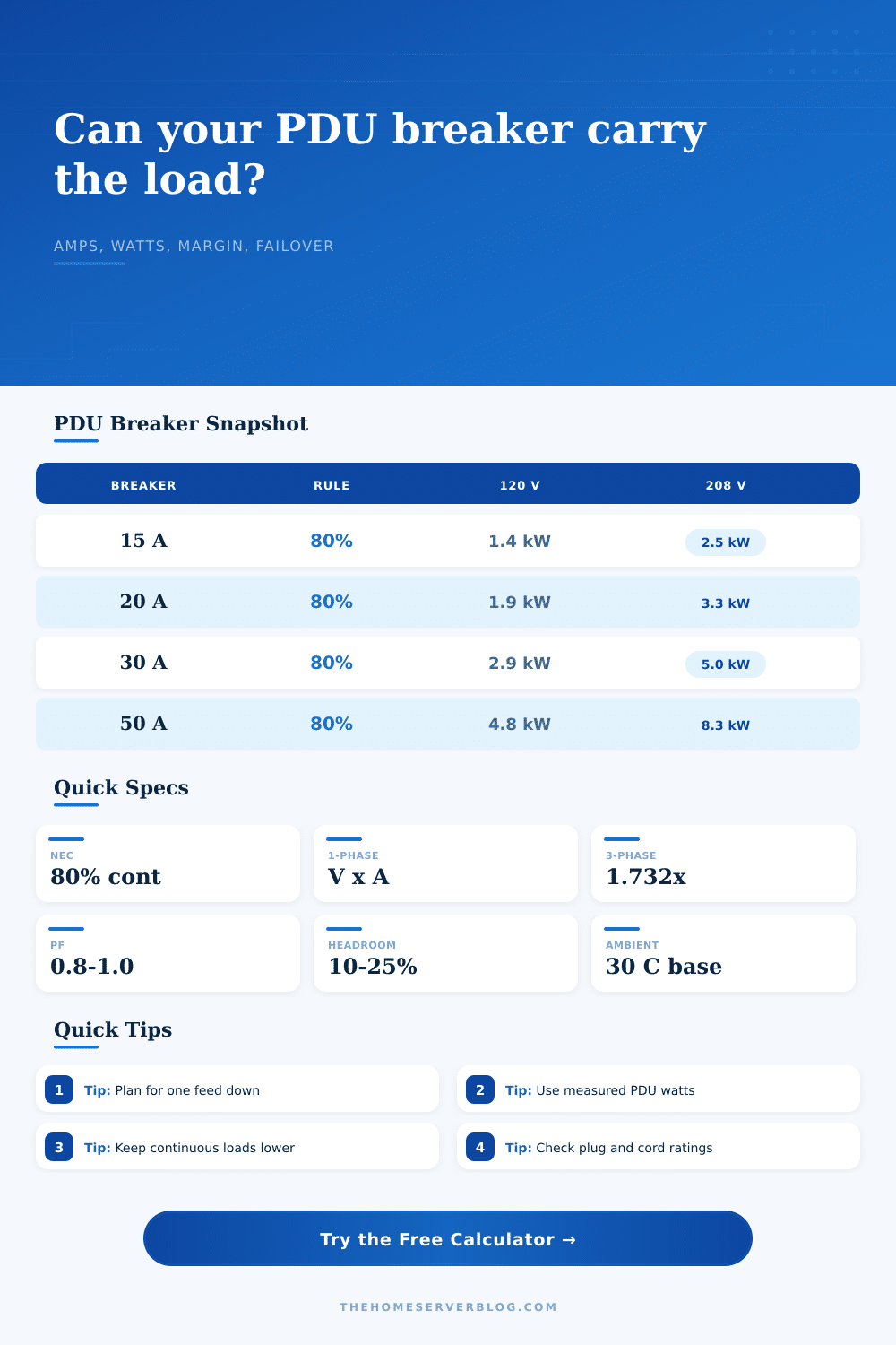
| Breaker | 80% continuous | 120 V watts | 208 V watts |
|---|---|---|---|
| 15 A branch | 12 A | 1,440 W at PF 1.0 | 2,496 W at PF 1.0 |
| 20 A branch | 16 A | 1,920 W at PF 1.0 | 3,328 W at PF 1.0 |
| 30 A branch | 24 A | 2,880 W at PF 1.0 | 4,992 W at PF 1.0 |
| 50 A feeder | 40 A | 4,800 W at PF 1.0 | 8,320 W at PF 1.0 |
For three-phase, multiply line-to-line voltage x amps x 1.732 x power factor.
| Ambient | Model factor | Planning meaning | Watch point |
|---|---|---|---|
| 30°C or cooler | 1.00x | Reference condition | Verify rack rear temperature |
| 31-35°C | 0.94x | Mild derate | Closets and ceiling spaces |
| 36-40°C | 0.88x | Noticeable derate | Warm electrical rooms |
| 41-45°C | 0.82x | Tight operating band | Summer peaks and exhaust mixing |
| 46-50°C | 0.75x | Conservative review | Manufacturer data required |
Ambient factors are planning approximations inspired by conductor ampacity tables, not a replacement for listed equipment data.
| PDU or circuit | Typical plug | Common use | Planning caution |
|---|---|---|---|
| 120 V 15 A | 5-15P / 5-15R | Small network rack | Shared room circuits trip easily |
| 120 V 20 A | 5-20P / L5-20 | Home lab branch | Check receptacle and cord rating |
| 120 V 30 A | L5-30 | Larger single-voltage PDU | Heavy current at lower voltage |
| 208/240 V 30 A | L6-30 / IEC 60309 | Servers and UPS input | Confirm PSU input range |
| 208 V 3-phase | L21-20 / IEC 60309 | Dense rack PDU | Balance line currents |
Nameplate breaker amps are only one part of the chain; plug, receptacle, cord, PDU, UPS, and panel ratings also matter.
| Redundancy mode | Usable feeds | Failover behavior | Capacity effect |
|---|---|---|---|
| Single feed | 1 | No alternate source | All load on one breaker |
| Active-active pair | 2 | Not sized for one feed down | Capacity roughly doubles |
| A/B redundant pair | 1 | One feed carries full rack | Capacity equals one breaker |
| Three feeds, lose one | 2 | Two remaining feeds carry rack | Use two breakers of capacity |
| 2N pair group | 2 | Half the feeds can be lost | Use half installed capacity |
Dual-cord servers often look comfortable in normal operation but must still fit one-side failover if A/B redundancy is required.
💡Two PDU derating tips
Plug it in, patch the cables, mount the servers, and build the rack. Everything look great until lights flicker or, worse yet, the breaker trip on a critical deployment. Your safety net here is a PDU breaker derating calculator.
This is not just about raw amperage. It’s about understanding how much power that can support in real world, not just an ideal laboratory environment where manufacturer conducted their test. People will see a 20 amp breaker, and they’ll assume it can handles 20 amps. They are wrong about that. According to the National Electrical Code, “continuous” loads must be calculated at 125 percent of circuit size. For example, a 20 amp breaker actualy only has 16 amps available on anything running more than three hours.
How to Use a PDU Breaker Calculator
The tool above does this math for you, using these rules without needing you to remember the code section numbers. It reduces your base capacity first then it lets you add on server. This is ambient derating. Electrical rooms are not typically cool enough to disregard effects of air temperature on copper’s conductivity. Because heat decreases copper’s conductivity, as ambient temperature increase, so does the breaker’s tendency to trip unnecesarily before reaching its rated capacity. At 40 degrees Celsius (you’re not going to have much room left in that closet), you won’t be recieveing rated current from your breaker. You can put an ambient temperature into the calculator, which will apply a reduction factor to take this into account. In other words, you’ll avoid the situation where server boots up, pulls its typical startup current draw, and trips the breaker just because it’s a hot day.
Next up is redundancy, which sounds counter-intuitive. Adding a second power feed does not double your capacity. Are you running an A/B redundant PDU? Make sure that one feed by itself can support whole rack when the other goes down. The calculator will let you model that failover state. What’s the total load? Can your single remaining breaker accommodates all that? Or are you simply spreading the load equally across both feeds? This matters too, because high availability setups can’t have any single point of failure, even in math.
Did I mention power factor? It’s more important then you’d expect. Even with moddern server power supplies, old and legacy devices can drag the power factor down to reduce available watts for each amp draw. That means you need to account for the power factor if you want an accurate wattage read. The tool lets you enter your power factor (typically around 0.8, 1.0) so it can give you a better idea of how many watts your hardware will actualy use. If you ignore it, you’ll plan optimistically, only to find that there aren’t nearly enough watts when you plug in all your gear. There are plenty of amps, but not enough watts.
The last protection from chaos is headroom. That’s room for growth, room for maintaining loads, and also room for inrush current. You can adjust the calculator to put aside some percent of reserve capacity. In other words, you’re never right on edge of your breaker. The margin of error could of been the difference between a functioning system and a middle-of-the-night page to reboot a tripped circuit.
There are some handy reference tables on the page that give immediate standards for typical configurations. For instance it shows you how much juice a 30 amp breaker puts out based off the phase and voltage. This lets you make comparisons ahead of time so you know what fits into your design without making a commitment. You’ll notice immediately if moving to 208 volts instead of 120 makes any difference to your available capacity. A little thing, but it counts when every watt matter in a crowded rack.
Ultimately, this all comes back to risk management in terms of power planning. It’s a balance between reliability, space, and cost. The calculator provides the information so you can make the trade-off with your eyes open. You don’t guess anymore; you know precisely how far you push it. You create the rack, run the numbers, go to bed, and rest assured that you’ve got the power for your stuff. There are no more trips and no more surprises. You have just solid power for the gear.