PoE PD Power Draw Calculator
Estimate powered-device draw, converter loss, cable voltage drop, PSE port wattage, PoE class headroom, and heat for cameras, access points, phones, bridges, and home-lab PoE gear.
PoE powered-device result
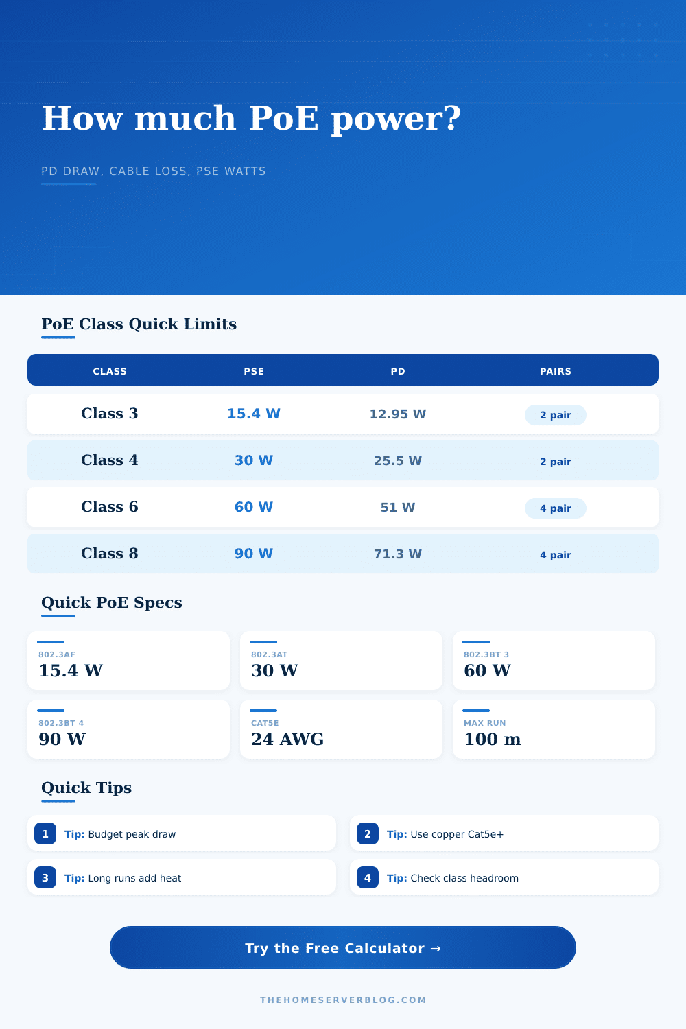
| PoE class | Standard type | Max PSE power | Max PD power |
|---|---|---|---|
| Class 0 | 802.3af Type 1 | 15.4 W | Up to 12.95 W at the powered device. |
| Class 1 | 802.3af Type 1 | 4.0 W | Up to 3.84 W for very low-power PDs. |
| Class 2 | 802.3af Type 1 | 7.0 W | Up to 6.49 W for phones and basic sensors. |
| Class 3 | 802.3af Type 1 | 15.4 W | Up to 12.95 W for standard af loads. |
| Class 4 | 802.3at Type 2 | 30.0 W | Up to 25.5 W for PoE+ access points and cameras. |
| Class 5 | 802.3bt Type 3 | 45.0 W | Up to 40 W for higher-power 4-pair loads. |
| Class 6 | 802.3bt Type 3 | 60.0 W | Up to 51 W for PTZ cameras, panels, and clients. |
| Class 7 | 802.3bt Type 4 | 75.0 W | Up to 62 W at the PD. |
| Class 8 | 802.3bt Type 4 | 90.0 W | Up to 71.3 W at the PD on compliant cabling. |
| Cable type | Planning resistance | PoE note | Best use |
|---|---|---|---|
| Cat6A solid copper, 23 AWG | 7.4 ohm / 100 m / conductor | Lower loss and better thermal behavior in bundles. | New ceiling AP and camera pulls. |
| Cat6 solid copper, 23 AWG | 7.8 ohm / 100 m / conductor | Good balance for PoE+ and moderate 802.3bt loads. | Home lab and office runs. |
| Cat5e solid copper, 24 AWG | 9.38 ohm / 100 m / conductor | Common baseline for af and at calculations. | Existing structured cabling. |
| Cat6 stranded patch, 24 AWG | 9.9 ohm / 100 m / conductor | Fine for short patch leads; avoid long hidden runs. | Rack patching. |
| Slim patch cable, 28 AWG | 23 ohm / 100 m / conductor | High resistance; keep short for PoE devices. | Short front-of-rack patching. |
| CCA or poor 24 AWG cable | 15 ohm / 100 m / conductor | Voltage drop and heating can be much worse than copper. | Avoid for PoE where possible. |
| PD family | Typical active draw | Common class | Peak driver |
|---|---|---|---|
| VoIP phone | 3 to 7 W | Class 2 or 3 | Screen, speakerphone, USB charging. |
| Fixed IP camera | 5 to 11 W | Class 3 | Night IR and analytics load. |
| Wi-Fi 6 AP | 10 to 18 W | Class 4 | Radio count and client load. |
| Wi-Fi 7 AP | 20 to 38 W | Class 4 to 6 | 6 GHz radio and full-rate mode. |
| Outdoor PTZ | 25 to 55 W | Class 5 to 7 | Heater, motors, blower, IR. |
| PoE mini switch | 8 to 25 W input | Class 4 to 6 | Downstream PoE pass-through. |
| Condition | Calculator field | Planning effect | Practical target |
|---|---|---|---|
| Ceiling plenum or warm attic | Temperature | Adds thermal reserve when ambient rises above 35°C. | Keep port load below about 80%. |
| Camera night mode | Peak factor | IR LEDs make peak higher than daytime watt readings. | Use 1.25x to 1.6x. |
| PTZ heater cycle | Duty cycle | Average heat can be far below winter peak draw. | Budget peak, size energy by duty. |
| Long cable run | Cable length | Line loss increases with current squared and resistance. | Use larger copper conductors. |
| 802.3bt four-pair load | PoE class | Current spreads across more conductor pairs. | Use Class 5+ for high PD loads. |
The heater comes on and you notice that the camera resets. Looking at switch port, you notice it’s still active. The motor kicked on along with infrared LEDs. Together, their total demand spike. Because the cable is long and has low-gauge copper wire in it, voltage drops out as the device loses power. It’s not the device; it’s the math.
Network people design for average consumption. They don’t factor cable resistance or peak surges into the calculations. Go past what says “access point” on its rear. This is why the calculator does the math on peak draw vs port limits, and includes the hidden cost of power delivery. This also includes heat effects on the cabling itself; voltage drop, inefficiencies in converters, etc. No, you don’t need to remember Ohm’s Law to play with it. You just need to know what each input mean. There is also a preset that provides some guidance as a baseline (the measured watts count more).
Why Your Camera Loses Power
But if you’re running a Wi-Fi 7 access point that pulls twenty-four watts idling, you’re pretty much maxed out using standard PoE+. Longer cable runs loses more power to heat, which leaves less signal reaching the radio. The cable gauge matter a lot with these deployments. While many of us assume that Cat6 and Cat5e is the same thing because both work fine for delivering data, they aren’t. Because the wires are different thicknesses, the resistance is different, and thus voltage drop is different. Over a hundred feet, this results in reboot loops; on a shorter run, there’s little noticeable effect. For data runs, it allows you to switch between stranded versus solid copper patch cable, as well as copper-clad aluminum; the calculator will display precisely how much headroom you lose (and typically isn’t worth it).
For example with PTZ cameras, peak versus average power becomes relevant. During the day, a camera may draw ten watts on average, but during nighttime when the camera turns and heaters cycle, it will briefly draw 40 watts. The port doesn’t care about average power on your switch; it only cares about instantaneous maximum load. If that spike surpasses its budget, the device drop off. That’s why there is a peak factor input into the calculator, so you can build out the worst case scenario rather than the comfortable middle ground. Most engineers underrates this small detail.
The other neglected layer is thermal management. Cramming cables together in a tight ceiling plenum or tray bundle them, raising ambient air temp. More heat means more loss of power in the cable. This makes the cable warmer and hotter. This heats up the air and reduces its resistance. This continues into a feedback loop that slows down performance or shortens component life. You can use the tool to calculate how much energy and heat it produce each day, to help you know when to cool down, or to see why that switch gets hot in summer.
Where the rubber meets the road is on class choice. Basic devices with low power are in Class 3; PoE+ gear is in Class 4. High power is needed for complex security systems, heavy duty access points, and digital signage. This fall into Class 5 through 8. It’s all spelled out in the reference table, but what matters is matching the actual draw (not the marketing box) with an appropriate class. Over-assigning a low-power phone wastes your budget. Under-assigning a camera causes outages.
The science of budgeting for power has nothing to do with tech and everything to do with physics: “the material, the distance, the surge.” Plan for the worst case (the surge) and stop pursuing a phantom outage. You should of planned better. The goal is stability, not just connectivity. Stability is. Plan for what will cause an interruption (a.k.a., “account for the losses beforehand“). This ensures your camera stays online while the heater runs, which is all that matters.