HomeServerBlog pathway planner
Raceway Capacity Calculator
Estimate raceway cable fill, usable area, future spare capacity, compartment loading, separation allowance, bend penalty, cover access factor, and pull difficulty for low-voltage and mixed home lab pathways.
1Raceway presets
2Raceway, cable, spare, and pull inputs
Calculation breakdown
Fill pressure
3Raceway comparison grid
4Quick raceway metrics
Common conservative target for more than two conductors or cables.
Leaves room for patch additions and easier service pulls.
Extra corners make pathway capacity feel smaller in practice.
Power and data often need listed separation or distinct chambers.
5Raceway tables
| Raceway size | Inside area | 40 percent fill | Typical use |
|---|---|---|---|
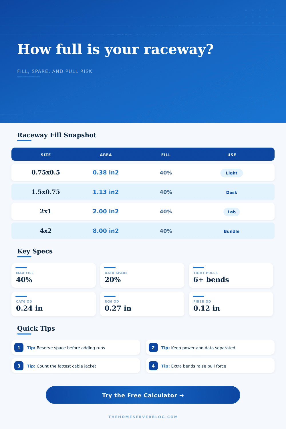
| 0.75 x 0.50 in | 0.38 in² | 0.15 in² | One or two small data drops where bends are minimal. |
| 1.00 x 0.50 in | 0.50 in² | 0.20 in² | Small office extension, single AP feed, or short camera branch. |
| 1.50 x 0.75 in | 1.13 in² | 0.45 in² | Desk, rack side wall, or several Cat6 cables with spare. |
| 2.00 x 1.00 in | 2.00 in² | 0.80 in² | Home lab bundle, media wall, or pathway with future runs. |
| 4.00 x 2.00 in | 8.00 in² | 3.20 in² | Large trunk route, basement distribution, or dense rack approach. |
| Cable type | Typical OD | Area each | Planning note |
|---|---|---|---|
| Cat5e UTP | 0.205 in | 0.033 in² | Useful for light bundles and legacy gigabit drops. |
| Cat6 UTP | 0.240 in | 0.045 in² | Common home server, AP, camera, and office cable. |
| Cat6A shielded | 0.330 in | 0.086 in² | Large jacket size can dominate raceway fill quickly. |
| Duplex fiber patch | 0.120 in | 0.011 in² | Small area, but bend radius and protection still matter. |
| RG6 coax | 0.270 in | 0.057 in² | Use actual jacket OD for quad-shield or flooded cable. |
| Condition | Capacity effect | Risk effect | When to upsize |
|---|---|---|---|
| More than 4 bends | Practical derate grows with each extra bend. | Pull force, jacket scuffing, and unlatching risk rise. | Upsize when the bundle also exceeds 70 percent of usable fill. |
| Mixed power and data | Divider or listed compartment reduces usable room. | Improper separation is a compliance and noise concern. | Upsize when the divider leaves one side overloaded. |
| High future spare | Current cable count is inflated before comparison. | Lower risk later, but requires more pathway now. | Upsize if the planned spare consumes all remaining capacity. |
| Shallow cover depth | Harder to close over bulky jacket stacks. | Cover bowing and service difficulty increase. | Upsize if cover depth is below the cable bundle diameter stack. |
| Project | Common bundle | Suggested raceway | Capacity target |
|---|---|---|---|
| Single desk drop | 2 to 4 Cat6 cables | 1.00 x 0.50 in or larger | Keep planned fill under 55 percent of usable area. |
| Wall-mounted rack | 10 to 18 Cat6 cables | 1.50 x 1.00 in or 2.00 x 1.00 in | Leave at least 20 percent spare cable positions. |
| Camera and AP trunk | 16 to 30 mixed low-voltage cables | 2.50 x 1.25 in or larger | Check bends and avoid overpacking corners. |
| Basement distribution | 30+ cables or mixed coax/data | 3.00 x 1.50 in or 4.00 x 2.00 in | Use multiple pathways if compartments become unbalanced. |
6Raceway planning tips
The mount looks clean and organized along the wall with your perfect surface raceway system. Great! You add another Cat6 cable for a new security camera, and go to close the lid. But it won’t snap back into place, it bows out and resists the latches. You force it closed because if you ever want to pull this wire out again, you’ll regret that you saved three inches. This is when raceway capacity stop being an easy geometry equation and turns into a usability nightmare.
Once you enter your dimensions into the calculator, it do all the math for you. No need for you to guess at conversions or coefficients.
Why Cable Capacity Is Hard
Filling a tube (or running cable) has become like packing a suitcase for most folks. If there’s room then stuff it full of cables. When box won’t close, add one and try again. The problem: Cables aren’t shirts; they don’t fold up neatly and fit together just so. They’re cylindrical objects with stiffness that doesn’t allow for perfect nesting, air gets trapped between cables. A shielded 100ft Cat6A will be bigger than a regular Cat6 (even though both can provides a gigabit), but most people only consider the number of conductors when selecting jacket size. A few mils in jacket thickness makes all the difference.
On paper, the difference may seem small. Multiply that by a dozen cables in a cramped space and you have yourself some precious square inches of wasted nothingness. Nobody thinks about that. They think in terms of diameter of wire, not outside diameter of the jacket. This tool corrects that as it lets you pick individual cable type. It adjusts area calculation based off how much room your insulation needs inside a piece of plastic tubing.
Capacity decreases as well with bends. Straight runs are forgiving. You can fit many more cables on a long linear path different than one that zigs and zags its way across three interior corners. Each bend multiplies friction exponentially. Each new bend increase the pulling force. If you’ve got a route with multiple bends (six or more), you’ll need additional space in those bends to allow the cables to articulate around corner without squishing their outer jacket. That means reduced effective capacity… Which is why the calculator asks how many bends you’re planning. Based off that number, it provides a risk rating. This tells you if you have a good chance of making it (the route will probably survive install) or if you should of upsize the entire raceway instead.
And then there’s the separation thing. For signal integrity as well as compliance, it’s never a good idea to have mains power and low-voltage data cables living in the same compartment. Sure, you can divide them but that means splitting your space down to even tinier areas.
Why is a 40 percent fill rule a conservative one? Because it allows for air, for movement, and for the future. Reserve twenty percent of your capacity for spares, and you’re not just being careful. You’re purchasing the right to add a drop without having to rip up the walls. The reference table on the page spells this out, showing what different raceway sizes translate into usable area under those conditions.
Finally there’s the check for cover depth. The fill limit may allow a shallow raceway, but it won’t if the thickness of stack of cables is greater than the depth of the channel. Geometry trumps area. You can have all the space in the world but it won’t seal the lid if it doesn’t work out. Make sure to always compare the inside height of the raceway to the vertical stack of your cables. A bowing cover mean you failed the test.
Only by planning the pull will your home lab wiring be serviceable years down the road. Go through the math, but rely on what your eyes see for the fit.