RF Cable Length Calculator
Calculate coax cut length from frequency, velocity factor, phase target, connector allowance, slack, delay, and RF attenuation for antenna feeds, phasing harnesses, SDR runs, and home lab RF links.
⚙Named RF presets
Presets fill real coax types, frequencies, velocity factors, and slack assumptions, then run the calculator.
📏Cable and phase inputs
RF cable length results
📊Calculated spec grid
The grid updates after each calculation and uses the selected coax velocity factor plus frequency-adjusted attenuation.
📚RF cable reference tables
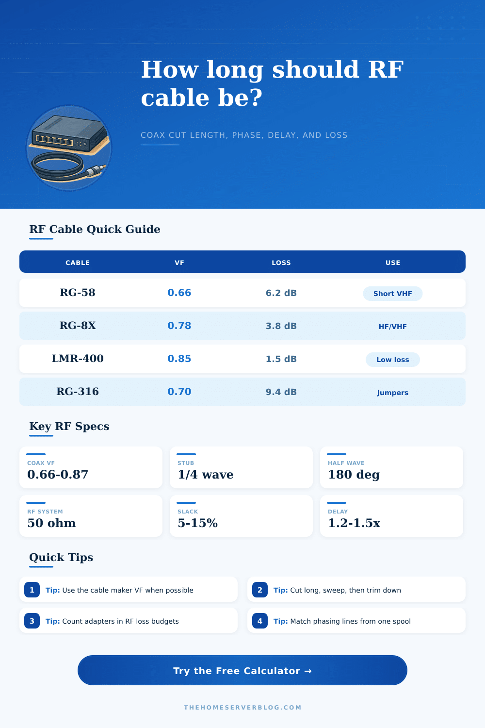
| Cable type | Typical VF | Loss at 100 MHz | Best home lab use |
|---|---|---|---|
| RG-58 solid PE | 0.66 | 4.9 dB / 100 ft | Short HF/VHF jumpers and test leads |
| RG-8X foam | 0.78 | 3.1 dB / 100 ft | Flexible HF and moderate VHF feed lines |
| RG-213/U | 0.66 | 2.2 dB / 100 ft | Durable outdoor HF and VHF runs |
| LMR-240 | 0.84 | 2.8 dB / 100 ft | Compact low-loss mast or rack cable |
| LMR-400 | 0.85 | 1.5 dB / 100 ft | Long VHF/UHF, SDR, repeater, and gateway runs |
| RG-316 PTFE | 0.70 | 7.5 dB / 100 ft | Short microwave pigtails and panel jumpers |
| RG-174 mini coax | 0.66 | 8.4 dB / 100 ft | Very short GPS, SDR, or embedded RF leads |
| 1/2 inch hardline | 0.88 | 0.8 dB / 100 ft | Permanent low-loss runs and repeater feeds |
| Electrical target | Degrees | Use case | Physical length formula |
|---|---|---|---|
| Eighth-wave section | 45° | Fine delay trim and compact matching sections | Wavelength x VF x 0.125 |
| Quarter-wave section | 90° | Stubs, transformers, phasing offsets, traps | Wavelength x VF x 0.25 |
| Half-wave section | 180° | Repeat impedance at a convenient distance | Wavelength x VF x 0.50 |
| Three-quarter wave | 270° | Longer phase offset with same quarter-wave phase | Wavelength x VF x 0.75 |
| Full wavelength | 360° | Phase repeat line or full-wave delay section | Wavelength x VF x 1.00 |
| Band or service | Frequency | Free-space wavelength | Quarter-wave in 0.66 VF coax |
|---|---|---|---|
| 40 meter ham band | 7.15 MHz | 137.6 ft | 22.7 ft |
| 20 meter ham band | 14.2 MHz | 69.3 ft | 11.4 ft |
| 2 meter FM calling | 146.52 MHz | 6.71 ft | 1.11 ft |
| 70 centimeter FM | 446 MHz | 2.21 ft | 0.36 ft |
| ADS-B receive | 1090 MHz | 0.90 ft | 0.15 ft |
| 2.4 GHz Wi-Fi | 2400 MHz | 0.41 ft | 0.07 ft |
| Project scenario | Typical cable | Planning focus | Practical limit to watch |
|---|---|---|---|
| SDR roof antenna to home server | LMR-400 | Loss and lightning panel routing | UHF loss above 1 GHz |
| Dual vertical phasing harness | RG-8X or RG-213 | Equal phase and equal physical routing | Connector repeatability |
| Bench VNA test jumper set | RG-316 | Repeatable delay and connector wear | Short pigtail loss |
| Repeater duplexer to antenna | Hardline | Low loss and power handling | Bend radius and grounding |
| GPSDO reference distribution | RG-58 or LMR-240 | Delay matching between receivers | Temperature drift |
💡RF planning tips
The length of an RF cable are a critical factor in the installation of radio frequency (RF) systems. The length of an RF cable can significently impacts the performance of the radio system. If the length of the RF cable is either too long or too short, it can impact the system in several ways.
For example, if the length of the RF cable are incorrect, it might impact the amount of power that reaches an antenna. It might also impact the signal strength at the antenna during reception. Additionally, using an incorrect length of RF cable can cause extra heats to be created within the coaxial RF cable.
Why RF Cable Length Matters
To ensure the system work as the designer intended, the designer should ensure the length of the RF cable is accurate. The physical length of the RF cable is not necessarily the same than the electrical length of the cable. The electrical length of the cable is the distance that the signal travel within the RF cable.
For most coaxial RF cables, the velocity factor will cause the electrical length of the cable to be different from the physical length of the cable. The velocity factor is a percentage that indicate at what rate a signal slows down within a specific type of coaxial RF cable. By using the velocity factor, the user can calculate the correct electrical length of the RF cable.
Additionally, temperature can impact the length of the RF cable. Heat will make the RF cable expand and cold will make the RF cable contract. The changes in length that result from changes in temperature are generally small but can still impact the phase of the signal, especially in applications that require great precision in that phase.
To properly use an RF length calculator to determine the length of the RF cable, the user should choose the correct mode. Depending on the application of the RF cable, it can be used in one of two modes. If the RF cable is to be used as a tuned stub or a phasing section, the length must be an exact electrical length.
If the RF cable is to be used as a feed line, the user will use the physical length of the cable. Additionally, within the RF length calculator, the user will need to enter the frequency of the signal. This value will allow for the wavelength of the signal to be determined.
Additionally, the user will need to enter the target phase that the signal should achieve into the calculator. This value will allow the calculator to determine the number of degrees of the wavelength that should be used for the RF cable. Finally, allowances need to be made for connections between the RF cable and the rest of the system.
Although RF length calculators are helpful and can account for many different variables within the RF system, there is some that cannot be accounted for. For instance, the environment in which it will be used may affect the length of the RF cable. An RF cable that runs near metal may experience changes to the impedance of the cable.
Additionally, the RF cable may be required to make sharp bends which could also impact its velocity factor. Additionally, the type of connectors that are used may have an impact on the length of the RF cable. Poorly soldered connectors or connectors of different depths may lead to mismatches in the system.
These types of issues can cause two RF cables of the same length from the same spool to behave differently within the RF system. To account for these types of variables, it is generally a good idea to cut the RF cable to be slightly longer than the length that is calculated by the length calculator. By doing this, the user can test and trim the RF cable to the correct length.
As with almost any system, there will be a loss of signal that passes through the RF cable. Additionally, the longer the RF cable and the higher the frequency of the signal, the higher the rate at which signal loss will occur. Another effect of the higher frequency of the signal is that there will be a loss of energy in relation to the length of the RF cable.
Thus, RF cables that work well at high frequencies may not work as well at low frequencies. The length calculator can calculate signal loss so that the user can view the delivered power of the signal. Based on this value, a decision can be made as to whether or not a heavier RF cable is needed.
In systems in which signal loss is generally small and insignificant, it may not matter what the value is. Yet in systems like repeater or gateway systems, signal loss will matter because of the weakness of the signal at this point in the system. The length of phasing harnesses has strict requirements.
A phasing harness is generally used to connect two or more antennas to the same RF source. If the RF cables that connect these antennas to the source do not have the same electrical lengths, the antennas will radiate a distorted signal. To avoid these problems, the user should use the same brand and spool of RF cable.
Additionally, the same lot of connectors should be used. Reference tables exist to give context to the values that is generated by RF length calculators. One type of reference table will illustrate signal loss through different types of RF cables at the given frequency.
Another type of reference table will illustrate the reasons that the physical length of a quarter-wave section of an RF cable changes with the change in the frequency of the signal. For instance, a quarter-wave section of an RF cable at 146 MHz will not have the same physical length as a quarter-wave section of an RF cable at 7 MHz. These types of reference tables will allow the users of the calculator to determine if the length of the RF cable that is calculated for their project is physically possible.
While the length calculator provides a good start to determining the length of an RF cable for a project, the calculator does not account for every single variable. For instance, it cannot account for the variables related to temperature, connectors, or routing of the RF cable. Thus, the length that is calculated by the length calculator is only an estimate.
As such, the RF cable should be cut, tested, and adjust accordingly to ensure that the theoretical length of the cable becomes the actual length of the RF cable that is used in the project.