Signal Loss Calculator
Estimate RF and network-link losses from coax cable attenuation, connectors, splitters, amplifiers, antenna gain, dBm levels, and required link margin.
Signal Budget Breakdown
| Cable preset | Typical loss at 100 MHz | Typical loss at 1 GHz | Common use |
|---|---|---|---|
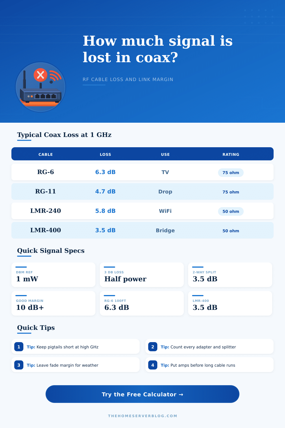
| RG-6 Quad Shield | 2.0 dB / 100 ft | 6.3 dB / 100 ft | TV, CATV, MoCA, OTA |
| RG-11 | 1.5 dB / 100 ft | 4.7 dB / 100 ft | Long 75 ohm drops |
| RG-59 | 3.4 dB / 100 ft | 12.0 dB / 100 ft | Short legacy video |
| RG-58 | 3.8 dB / 100 ft | 13.0 dB / 100 ft | Short VHF/UHF jumpers |
| RG-213 | 1.8 dB / 100 ft | 6.6 dB / 100 ft | HF/VHF radio feedline |
| LMR-240 | 1.6 dB / 100 ft | 5.8 dB / 100 ft | WiFi pigtails, small radios |
| LMR-400 | 1.0 dB / 100 ft | 3.5 dB / 100 ft | Outdoor WiFi and backhaul |
| 1/2 in Heliax | 0.55 dB / 100 ft | 1.9 dB / 100 ft | Low-loss tower runs |
| Splitter or component | Planning loss | Power effect | Where to include it |
|---|---|---|---|
| Inline barrel or adapter | 0.1 to 0.5 dB | Small but cumulative | Connector count or extra loss |
| 2-way splitter | 3.5 dB | About half power | Splitter dropdown |
| 4-way splitter | 7.0 dB | About quarter power | Splitter dropdown |
| 8-way splitter | 10.5 dB | About one-eighth power | Splitter dropdown |
| Attenuator pad | 3 to 20 dB | Intentional reduction | Use amp as negative gain |
| Mast or distribution amp | 10 to 30 dB | Raises level, may add noise | Amplifier gain |
| Margin result | Meaning | Typical action | Planning note |
|---|---|---|---|
| 20 dB or more | Very strong | Check overload risk | Good for long-term fade |
| 10 to 19.9 dB | Healthy margin | Build as planned | Common home lab target |
| 3 to 9.9 dB | Usable but tight | Shorten cable or reduce splits | Weather may matter |
| 0 to 2.9 dB | On the edge | Add gain or better coax | Expect intermittent drops |
| Below 0 dB | Below target | Redesign the path | Receiver target not met |
| dBm value | Power | 50 ohm voltage | Common reference |
|---|---|---|---|
| -90 dBm | 1 pW | 7.1 uV RMS | Weak radio signal |
| -60 dBm | 1 nW | 224 uV RMS | Usable WiFi level |
| -30 dBm | 1 uW | 7.1 mV RMS | Small RF signal |
| 0 dBm | 1 mW | 224 mV RMS | Lab and RF reference |
| 30 dBm | 1 W | 7.1 V RMS | Low-power transmitter |
Signal loss occur in every coaxial cable run, whether you are transmitting a television signal from an antenna to a television or from one radio to another radio across the roof. The amount of signal loss between a transmitter and a receiver will determine whether the signal link will work or fail. Understanding the various cause of signal loss and the amount of control over signal loss will allow you to reduce the uncertainty of signal loss.
Every coaxial cable has a loss rate for signal power that is transmit through that coaxial cable. The loss rate of a coaxial cable increases as the frequency of the signals transmitted through that coaxial cable increase. For instance, a coaxial cable run may work at 100 megahertz, but that same coaxial cable run may not allow the signals to travel as far at 2.4 gigahertz or 5 gigahertz.
Why Coaxial Cables Lose Signal
Higher rate of frequency of the signals traveling through a coaxial cable allow the signal to travel more close to the surface of the conductor, and the conductor will remove more energy from the signal. Coaxial cables of different construction will lose signal energy differently. For instance, a coaxial cable that contain a low-loss foam dielectric and a shield will allow more of the signal to reach its destination than an older type of coaxial cable that contains a solid polyethylene dielectric.
Consequently, a hundred-foot length of one coaxial cable may lose three decibels of signal power, while a hundred-foot length of a different coaxial cable may lose six decibels of signal power. Connectors will also cause signal loss. Each connector will allow for a small amount of loss in signal power.
The more connectors placed in a coaxial cable run, the more signal loss will occur. Signal loss will also occur through the use of splitters. A splitter will divide the signal strength of a signal so that the signal is sent to more than one device.
For instance, a two-way splitter will divide the signal so that each device receives half of the signal power of the original signal. Thus, the more split created by using splitters, the more signal loss occurs. Lastly, signal loss can also happen with the use of an amplifier and antenna.
An amplifier will increase the signal strength to overcome signal loss over a coaxial cable, but if you dont place the amplifier in the correct location, it will not be able to effectively overcome signal loss. Coaxial cables have specific order of components that will allow the signal to travel the distance from the transmitter to the receiver. For instance, if a preamplifier is mounted near the antenna, the preamplifier will amplify the signal before it ever travels through the coaxial cable.
Alternatively, if an installer places an amplifier after a long run of coaxial cable, the amplifier will also amplify the noise and interference that was introduced into the coaxial cable. Thus, receive systems may incorporate amplifiers early in the system, but transmit systems will benefit from placing the components as close to the radio as possible. A planning margin must be included in the system to account for variables.
For instance, changes in the temperature of the coaxial cable will change the resistance of the conductor. Additionally, if there is moisture in a connector, that will also reduce the signal strength. Furthermore, if there are leaves growing on a coaxial cable, that will also reduce the signal strength of the signal traveling through that coaxial cable.
In order to account for these variable, engineers will include a planning margin; many use a target planning margin of ten decibels so that any changes in environment will not impact the signal link. In addition to the specifications of the coaxial cable, there are other factor that may impact the signal strength. For instance, the coaxial cable may become kinked during installation.
Additionally, the connectors may become overtightened or become loose. Finally, a ground block may become corroded due to exposure to teh weather during the winter months. While a link budget calculator will help to manage the math behind the signal, giving engineers the ability to focus on the trade-offs in signal design, these variables is introduced into the signal.
When choosing a coaxial cable, you must determine where spending money on a coaxial cable will provide the most improvement. For instance, the difference in the RG-6 and the LMR-240 cable may be challenging to see over a short jumper cable, but the difference between those two type of coaxial cable may be the difference between receiving a signal over a 150-foot rooftop coaxial cable run. Additionally, the more expensive coaxial cables will allow installers to handle the coaxial cable with less difficulty, but the coaxial cables will also have lower loss rates so that the signal does not have to travel through an amplifier to reach the destination device.
The impedance of the coaxial cable will impact the signal loss of the system. Coaxial cables used for television signals use an impedance of 75 ohms. In contrast, two-way radio and data links uses an impedance of 50 ohms.
Mixing components of different impedance value will create signal loss due to signal reflection. This signal loss will reduce the power that is delivered to the destination device and the signal will be reflected back to the source. Additionally, the reflected signal may impact the signal source, especially if the signal source is a transmitter.
Thus, to remove this variable from signal loss calculations, the entire signal path can be maintain at one impedance value. Finally, another variable that must be considered is the sensitivity of the receiver. The target planning margin will determine how much variation in environmental factor will not impact signal loss.
For instance, if there is a large planning margin, small changes to the environment will not lead to signal loss. Conversely, if the planning margin is small, any additional components along the signal path will increase the chance of signal loss. Thus, monitoring the receive level will allow the installer or the system designer to determine the impact of changing the type of coaxial cable, the length of the coaxial cable, or the number of split in the signal path.