Signal Propagation Delay Calculator
Estimate travel time through copper, fiber, air, PCB traces, and mixed signal paths with device delay and skew checks.
Signal Delay Results
Calculation Breakdown
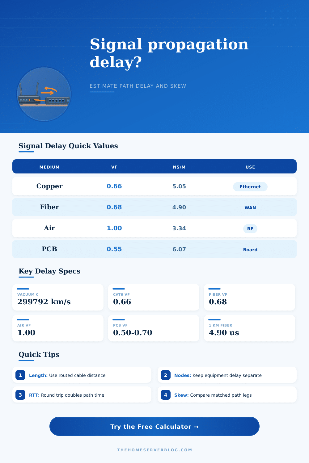
| Medium | Typical velocity factor | Delay per meter | Common use |
|---|---|---|---|
| Twisted-pair copper | 0.64 to 0.72 | 4.63 to 5.21 ns/m | Ethernet, control wiring, serial data |
| Coaxial copper | 0.66 to 0.85 | 3.93 to 5.05 ns/m | RF feeders, lab instruments, video |
| Single-mode fiber | 0.67 to 0.69 | 4.84 to 4.98 ns/m | WAN, campus backbone, long trunks |
| Air / free space | 0.997 to 1.000 | 3.34 ns/m | Wi-Fi, microwave, radio links |
| PCB microstrip | 0.55 to 0.70 | 4.77 to 6.07 ns/m | Outer-layer high-speed board traces |
| PCB stripline | 0.45 to 0.60 | 5.56 to 7.41 ns/m | Inner-layer clock and data routing |
| Preset | Medium | Distance | Primary delay focus |
|---|---|---|---|
| Home Cat6 Run | Copper UTP | 30 m | Patch lead plus switch latency |
| Rack DAC Link | Twinax copper | 3 m | Very short cable, device delay dominates |
| Campus Fiber | Single-mode fiber | 2 km | Backbone one-way transport |
| Metro Fiber RTT | Single-mode fiber | 25 km | Round-trip path latency |
| Wi-Fi Room Hop | Air | 15 m | RF propagation before MAC overhead |
| PCB DDR Pair | PCB microstrip | 75 mm | Skew tolerance and route matching |
| Quantity | Formula | Typical unit | What it tells you |
|---|---|---|---|
| Signal speed | c multiplied by velocity factor | m/s or km/s | Effective travel speed in the medium |
| One-way propagation | Distance divided by signal speed | ns, us, ms | Physical travel time only |
| Total selected delay | Propagation plus device and repeater delays | ns, us, ms | End-to-end timing for the selected mode |
| Round-trip delay | One-way total multiplied by 2 | ns, us, ms | Useful for ping and control-loop timing |
| Path skew | Length mismatch divided by signal speed | ps or ns | Timing difference between paired routes |
| Path scale | Example distance | Propagation range | Planning note |
|---|---|---|---|
| Board trace | 50 to 300 mm | 0.25 to 2 ns | Important for clocks, buses, and matched pairs |
| Rack cable | 1 to 5 m | 5 to 25 ns | Usually smaller than switching delay |
| Home cable run | 20 to 90 m | 100 to 455 ns | Visible in precision timing, tiny for browsing |
| Campus fiber | 1 to 5 km | 5 to 25 us | Distance begins to matter for storage and sync |
| Metro / regional | 20 to 100 km | 0.10 to 0.50 ms | Round-trip delay doubles the physical path |
When we talk about latency, one thing to remember is that this is the friction on your digital interaction: Why do stock traders puts their server next to an exchange? Because the connection is faster. Why does video calling get laggy if people are located too far away? Because of latency. Distance do matter, even though light is fast; people think data gets there instantaneousy. Try out the signal propagation delay calculator.
It calculates the time it takes for a pulse to travel through air, fiber, or copper medium. You’ll learn something about your network path… Not the abstract promise of gigabit speed, but the physical reality. So the basic idea is velocity factor, the reduction in signal velocity caused by the medium relative to a vacuum. Vacuum is the fastest thing there is but the fact that you never send data through nothing means we loses something.
Why Distance Makes Your Internet Slow
Electromagnetic waves gets slowed down as they travel through copper cabling where the conductor and insulation interact. Copper cable slows signals down significantly, but fiber optics is better, letting light move at about sixty-eight percent of its vacuum speed. It does, traveling some 68% of the speed of light in a vacuum. That’s pretty good; still it adds up and you can measure the delay over time in long runs.
Clocks run too fast for printed circuit board traces and they also slow things down. Software isn’t going to help: it’s a hard physical limit. The second thing is youve got to tell the truth about how far apart things are. That thirty meter cable isn’t actualy going to run thirty meters. Service loops dangle off racks. Cable trays turns corners. The slack coils up underneath someone’s desk until it’s needed again for a repair. Those all adds more feet, increasing propagation time.
But nobody think about counting that extra distance. This applies unless they are dealing with something where timing really matters, like industrial control systems or financial trading. In those cases, it makes all the difference. You feed it the true, routed length and the tool does the rest. It converts from the distance that shows up on floor plan into the one you’re really going to get.
Noise also come into play with hardware. Repeaters or routers or switches processes the signal, which introduces its own delays at every hop. This is called latency. It comes from buffering packets or checking headers rather than being physical, meaning it does not depend on microseconds of light zipping across fiber. It depends off engineering decisions.
Device latency can helps you isolate where your bottlenecks are, is the network slow because light is slow? Or did some switch get too cheap so it buffers everything for a half a millisecond? That’s a different fix. Another trap is skew. If two signals takes different paths to get to the same place, then they’ll have arrived at slightly different times by the time they gets there. That creates a mismatch that can corrupt data in high-speed serial links, or mess with clock domains in digital logic.
You want to match your path lengths inside some narrow tolerance so that your bits arrives together. Then check your skew margin against the tolerance of your hardware and prevent those small bugs from haunting you later. For most internet applications, propagation delay appears to be unimportant; a few microseconds of added latency have minimal impact on streaming or browsing. But for real-time industrial automation, telemedicine, or high-frequency trading, each nanosecond counts.
A fraction-of-a-second delay might mean the difference between profit and loss. When performance really matters, know the physics of what’s traveling your way and optimize accordingly. You may not be able to outpace the speed of light but you can avoid wasting time with equipment that doesn’t honor it. Awareness converts a black box into something you command. Not the other way around.