Spine Leaf Oversubscription Calculator
Model a routed spine-leaf fabric from leaf access ports, server NIC speed, spine count, uplink speed, ECMP path limits, N-spine failure, east-west traffic, and target oversubscription ratio.
Spine-leaf fabric results
| Fabric ratio | Typical fit | Traffic pattern | Planning note |
|---|---|---|---|
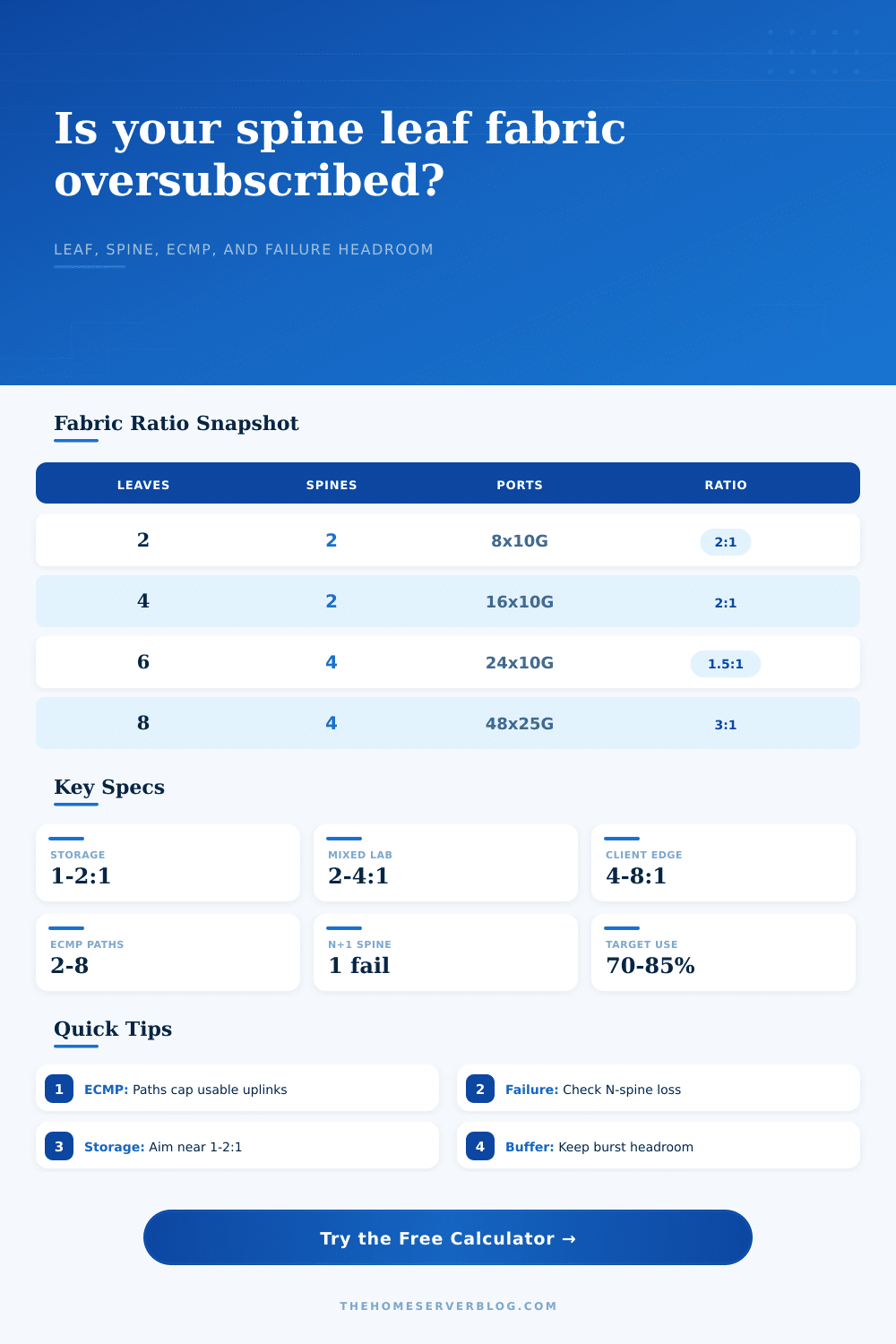
| 1:1 to 1.5:1 | Storage, GPU, dense virtualization | Heavy east-west | Good for low-latency fabrics where many hosts can talk at once. |
| 1.5:1 to 3:1 | General server racks | Mixed east-west and north-south | Common target for home labs running hypervisors and shared storage. |
| 3:1 to 6:1 | Client, AP, and service edge | Bursty demand | Works when active hosts are statistically multiplexed and bursts are short. |
| 6:1 plus | Low-duty clients or IoT | Mostly idle edge | Needs monitoring and clear failure expectations before production use. |
| ECMP limit | Effect on leaves | Failure impact | Best check |
|---|---|---|---|
| Paths equal uplinks | Every physical uplink can carry routed flows | Capacity falls with failed spines | Verify routing table and hashing support the intended path count. |
| Paths below uplinks | Some links may be standby or unused for a destination | Failure may expose hidden oversubscription | Use the ECMP path count, not just cable count, in planning. |
| Spines below uplinks | Leaf cannot use more spine paths than live spines | N-spine loss cuts every leaf | Run the calculator with one and two failed spines. |
| Hash skew | Large flows may not spread evenly | One hot path can queue early | Add reserve buffer for backups, replication, and elephant flows. |
| Server port speed | Common uplink | Leaf example | Practical note |
|---|---|---|---|
| 1G or 2.5G | 10G or 25G | 24 to 48 client ports | Oversubscription is usually acceptable for clients and AP aggregation. |
| 10G | 25G or 40G | 16 to 32 server ports | Good used-switch range for home labs and compact server racks. |
| 25G | 100G | 24 to 48 server ports | Common data-center style ratio with four to eight uplinks per leaf. |
| 100G plus | 400G or 800G | AI, GPU, or storage nodes | Failures and ECMP limits matter more than nominal switch capacity. |
| Design choice | Raises capacity | Improves resilience | Tradeoff to watch |
|---|---|---|---|
| Add uplinks per leaf | Yes, if ECMP and spines allow them | Sometimes | Port use, optics, DAC length, and hashing balance. |
| Add spine switches | Yes, when leaves have matching uplinks | Yes | More routing adjacencies and more cabling per leaf. |
| Increase uplink speed | Yes | No by itself | Transceiver support, breakout mode, and switch buffers. |
| Lower target utilization | No | Operationally | Requires more links to leave queue and burst headroom. |
When you build a spine leaf fabric, paying attention to the wiring behind the wall (i.e., the switches) matter as much as what’s in front of it (the switches). Fast server ports paired with powerful top of rack switches won’t matter if the path to the rest of the system is narrow. That’s where the concept of oversubscription comes into play.
Oversubscription isn’t a flaw; it’s a design choice. When the ratio becomes too great, that’s the issue. Problems also occurs when one failure collapses the bandwidth model. And most builders focuses on the raw number of gigabytes without regard for how traffic flows from the bottom to the top of the stack. They presume all uplinks function equally at every moment, which is rare.
How to Design a Good Network
After plugging in your spine config, leaf count and leaf port speeds into the calculator above, it do the rest of the math for you. No need to bother with conversion or coefficient guesses. What’s even better is that it makes you face reality about what you can realy use vs what physical capacity you have.
Having eight physical uplinks from your leaf switch doesn’t mean you has eight times the bandwidth. Your routing protocol will support only so many equal cost multi path (ECMP) paths, and that number might be four. So in fact you have half the bandwidth you paid for. And the tool lets you specify ECMP limits, accounting for this reality.
The tool also lets you model what happens when a spine fails. In fact, your entire fabric should still meet your target utilization even after losing one spine. If not, you are designing for the best case scenario. That never lasts long enough in production so your design isn’t robust.
However, when you get into storage traffic, everything changes. Block storage and object storage demand high throughput and low latency. They don’t care about your budget constraints. If you’re doing Ceph, iSCSI, or NFS, you want an oversubscription ratio approaching one to one. In other words, the sum of the bandwidth of all your server ports are equal to the sum of the bandwidth of all your uplinks. Why? Because you don’t have time for statistical multiplexing. When each host is talking to every other host at once, you need raw pipe. More optics, more cables, more switch ports; it cost money. But it gets things done. That’s why the calculator shows you that you’ll have a high bisection bandwidth requirement in this case.
What is bisection bandwidth? It’s the max amount of data that can flow between two halves of the fabric at the same time. If it’s low, your storage array will stall while it tries to replicate itself.
Client networks are different. Your end user devices don’t max out their links for hours at a time. They burst. They burst when they need something, check email, stream a video, and then they sit idle for twenty minutes. You can aggressively oversubscribe because of this. On desktop aggregation or Wi-Fi access points, four to one works fine. Six to one might work fine. The key is to monitor. You want to make sure that your bursts don’t line up with each other perfectly in all users. If they do, you will have congestion.
The calculator lets you specify a target usage percentage. Keep it below eighty percent and you’ve got headroom for backup jobs, replication traffic, and the occasional elephant flow that ignores your hashing algorithms.
The other big factor is east west traffic. In today’s data centers most of the traffic doesn’t go out to the internet anymore. It remains within the fabric, moving between application servers and database clusters. That traffic hammers your uplinks if your east west ratio is more high. There’s a field in the tool for that ratio. Enter your east-west percentage. Seventy percent? Then it will adjust the effective load applied to the spines. This lets you know if your spine count meets your needs.
If not, what do you do? Add more uplinks per leaf? Or add more spines? Each has a tradeoff. Adding more uplinks increases cabling complexity (and maybe hash skew). Adding more spines adds more routing adjacencies and management overhead.
Headroom gets forgotten too. Hashing to the same flow fills up buffers. Perfect ECMP doesn’t mean no imbalance. Add a reserve buffer and the calculator does that for you. Start with ten percent. That’s the skew. That’s the unexpected backup job. That’s the day when it all goes wrong at once. Planning without headroom is an invitation to packet loss. You wouldn’t of wanted to find out what your limits are after they’re exceeded.
This is what the page does. The reference tables on the page lay it out with typical ratios for different use cases. The bottom section is for storage. The top section is for the client edge. The middle section shows mixed workloads. Treat these as a sanity check. A ratio of eight to one for a virtualization cluster? Something’s wrong. You’re asking for trouble. Tweak the inputs. Add a spine. Upgrade the uplink speed. Do it again. Risk management is what design is all about. It is a tradeoff of cost against performance. It is a tradeoff of complexity against resilience. The calculator lets you quantify that tradeoff. It lets you turn fuzzy worry into hard numbers. See exactly how much capacity you lose with a spine down. See whether your ECMP limit is throttling your bandwidth. When you see the numbers, it’s an easier decision. No more guesswork. More engineering.
Finally, a nice piece of fabric just goes unnoticed. It takes whatever you can give it and doesn’t complain. It withstands the spikes. The failures. It does not drop packets. Not the highest throughput on paper, but the best performance in real life. Look at the failures. Look at the ratios. Then build it.