ToR Switch Port Count Calculator
Size top-of-rack switch ports for servers, NIC lanes, storage links, out-of-band management, uplinks, patch panels, spares, breakout ports, and A/B redundancy.
ToR port count results
| Rack pattern | Typical downlinks | Uplinks to reserve | Port planning note |
|---|---|---|---|
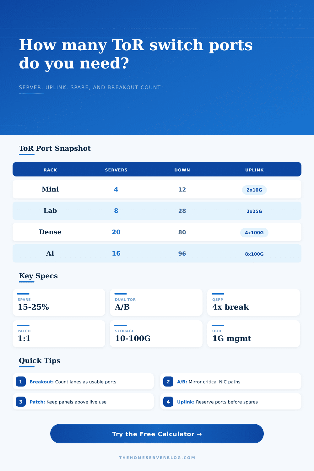
| Small home lab | 4-12 server ports | 2x10G or 2x25G | One compact ToR can work if OOB is separate. |
| Virtualization rack | 16-48 server ports | 2-4 high-speed ports | Dual ToR split NICs keeps maintenance simple. |
| Storage-heavy rack | 32-80 server and storage ports | 4-8 uplink ports | Separate storage links can dominate switch count. |
| Accelerator rack | 64-128 mixed lanes | 4-12 100G ports | Breakout and native QSFP planning matter early. |
| Breakout option | Consumed cages | Usable lanes | Best fit |
|---|---|---|---|
| No breakout | 0 QSFP cages | 0 extra lanes | Simple racks with matching server NIC speeds. |
| 1x4 breakout | 1 QSFP cage | 4 SFP lanes | Adding a few 10G or 25G server ports. |
| 2x4 breakout | 2 QSFP cages | 8 SFP lanes | Mixed storage and compute with limited cages. |
| 4x4 breakout | 4 QSFP cages | 16 SFP lanes | Dense ToR where lane count beats port label count. |
| 8x4 breakout | 8 QSFP cages | 32 SFP lanes | High-density 25G racks or clustered storage. |
| Redundancy mode | Switch count behavior | Port effect | Planning use |
|---|---|---|---|
| Single ToR | Minimum switches | No duplicated fabric | Lowest cost lab or noncritical rack. |
| Dual split | At least two switches | Server NICs divide across A/B | Most home lab and small colo racks. |
| Dual full mirror | At least two switches | Each side must carry the full plan | Strict failover or active/standby cabling. |
| MLAG or vPC | At least two switches | Ports split, uplinks dual-active | Hypervisor, NAS, and firewall pairs. |
| N+1 maintenance | Adds one spare switch | Extra chassis capacity for swap windows | Racks where service access is hard. |
| Patch panel ratio | Meaning | Risk signal | Good practice |
|---|---|---|---|
| Under 80% | Plenty of landing space | Low | Label spare positions by future node type. |
| 80-100% | Panel nearly full | Medium | Leave blank keystones or fiber cassettes nearby. |
| 100-120% | Switch plan exceeds panel | High | Add a second panel before final cabling. |
| Above 120% | Cabling design mismatch | Very high | Recount OOB, storage, breakout, and uplink paths. |
How many times have you learned how to count ports the hard way? You rack up the servers and plug in the NICs, only to find that switch doesn’t have enough uplink ports for what you need. The patch panel resembles a birds’ nest and by the end of first day of deployment, all of those spare ports are spoken for.
It’s a constant problem in data center design, and something that can be easy avoided with just a little bit of planning. Plug in your server count, your breakout needs, and your redundancy goals, and this handy little tool will do the rest, avoiding that typical guesswork around coefficient and conversion computations.
Why Planning Ports Matters
The core of the problem is that top-of-rack switches are finite resources. The root cause is that rack switches has limited capacity. How much? You want to cram everything in there. This includes uplinks to the spines, server downlinks, storage connections, out-of-band management, and spare capacity.
That is what most folks miss. What I mean by that is they see how many ports are on the box and think that’s how many servers they’ll be able to plug into it. They won’t. Typicaly, each server requires two NICs because you want them redundant. There will need to be several port set aside for traffic exiting the rack. Unless you include these behind-the-scenes requirements in your design, your design fails from its own weight.
This is where redundancy alters the math considerabley. One switch is just dandy for a noncritical file server or home lab environment. Production environments, however, rarely allow for single points of failure. Chances are good that you’ll want an A/B configuration with half the server downlinks going to switch A and half going to switch B.
In such a scenario, each switch only deal with half the traffic. However, you must account for the number of ports on each side so you stay connected if one switch needs to be taken down for maintenance. By adjusting its calculation for your selected redundancy mode, the calculator shows this trade-off in port count requirements. It makes you consider failure states before they happen.
And then there’s the matter of breakout cables and speed. Many moddern switches are equipped with high-density QSFP cages capable of handling 400G or 100G, but many servers continue to have 10G or 25G SFP ports. Breakout cables allow you to split a single QSFP cage up into four smaller lanes. Sounds magical, right? But it comes at a cost in terms of how many cages is used.
Too many breakout cables and even though you might have lots of physical ports remaining, you’ll run out of cages. The page has a nice reference table that lays all this out clearly, explaining how many cages you give up for how many more usable lanes. It is a small detail, but an important one when you’re trying to squeeze density into a rack.
Move out-of-band management to a separate switch or VLAN. For administration, you need things like IPMI, iDRAC, or serial console ports. All of these are low priority and low speed. You don’t want to waste your precious high speed ports in your main data ToR switch on slow management traffic. Typically OOB gets shunted to its own cheap 1G switch or at least its own management VLAN.
You can use the tool to switch between these two setups and see how much headroom you get by keeping management traffic off the production fabric. Another quiet assassin is spare capacity. Maybe you have a rack with forty-eight ports planned out to the penny. All forty-eight are in use. Then you bring up an additional server. Whoopsie, better get yourself a full-blown switch!
Best practice says leave 15-20% (or more) of your ports free for spares. You need these for expansion, some temporary test nodes, or for re-cabling when someone’s doing maintenance on something. You should of bought big once so you don’t end up buying a second chassis because you’re too maxed out.
To conclude. Port counting isn’t simply arithmetic; it’s a matter of understanding both the physical limitations of the rack and the logical needs of the network. You must strike a balance between density, redundancy, and future growth. This port counter calculator gives you a good baseline from which to select your hardware. It will give you a clear snapshot of how many ports you need for servers, uplinks, and spares.
Use this to prevent the bird’s nest. Plan ahead and plan your ports before pulling the first cable. You’ll save yourself lots of headaches down the road. It’s a simple step but it makes all the difference in having a clean rack or a tangled mess.