Wi-Fi Cell Radius Calculator
Estimate the practical radius of one access point cell from band, EIRP, receiver sensitivity, wall loss, AP height, target RSSI, SNR margin, environment, density, and channel width.
Link and cell breakdown
Open
0 mLow clutter, path exponent 2.0, best for halls and open rooms.Home
0 mDrywall and furniture, path exponent 2.7, common AP plan.Apartment
0 mMore neighboring RF and walls, smaller reuse-friendly cells.Warehouse
0 mLonger aisles but reflective racks and higher mounting.Heavy
0 mMasonry, metal shelves, lab racks, and enclosure loss.The comparison grid recalculates the same AP and client target across each environment so you can see whether the design is wall-limited, noise-limited, or density-limited.
Good target for roaming phones, tablets, and real-time media.
Often enough for stable mid-to-high MCS data links.
Best channel width when many APs must reuse spectrum cleanly.
Practical fade and retry reserve for a home lab survey target.
| Planning target | Edge RSSI | SNR target | Practical use |
|---|---|---|---|
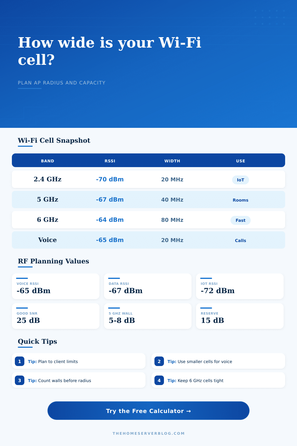
| Voice roaming | -65 dBm | 25 dB or better | Phones and video calls that need low retry rates between cells. |
| Reliable data | -67 dBm | 22 to 28 dB | Laptops, tablets, NAS browsing, dashboards, and general home office work. |
| Basic IoT | -72 dBm | 15 to 20 dB | Sensors, plugs, printers, and low-rate clients that tolerate latency. |
| High throughput | -60 dBm | 30 dB or better | Fast 5 GHz or 6 GHz rooms, local backups, and media workflows. |
| Band | Typical role | Cell behavior | Planning note |
|---|---|---|---|
| 2.4 GHz | Reach and IoT | Largest radius, lowest channel reuse | Use 20 MHz and avoid designing primary capacity around it. |
| 5 GHz | Main client access | Medium radius, good reuse | 40 or 80 MHz works well when AP count and neighbor RF allow it. |
| 6 GHz lower | Clean fast rooms | Smaller cells, cleaner spectrum | Great for same-room performance and careful multi-AP designs. |
| 6 GHz upper | Short high-rate cells | Smallest modeled radius | Keep AP placement close to where the fast clients sit. |
| Wall material | 2.4 GHz loss | 5 GHz loss | 6 GHz loss |
|---|---|---|---|
| Drywall interior wall | 2 to 4 dB | 3 to 6 dB | 4 to 8 dB |
| Brick or masonry | 6 to 12 dB | 8 to 16 dB | 10 to 20 dB |
| Low-E glass or mirror | 8 to 18 dB | 12 to 25 dB | 15 to 30 dB |
| Metal rack or appliance | 15+ dB | 20+ dB | 25+ dB |
| Channel width | Best fit | Noise penalty | Capacity tradeoff |
|---|---|---|---|
| 20 MHz | Dense AP layouts | 0 dB baseline | Lower peak rate, strongest reuse plan. |
| 40 MHz | Balanced homes | About 3 dB | Good compromise between rate and reuse. |
| 80 MHz | Fast rooms | About 6 dB | Higher rates, fewer independent channels. |
| 160 or 320 MHz | Short clean cells | 9 to 12 dB | Use only when spectrum and client support are excellent. |
Have you ever been in a Wi-Fi dead spot? If so, you probably recognize that feeling. You might be in a bathroom or perhaps behind an office closet when your phone says you have full signal bars, yet your video call freezes. When that happens, most people respond by purchasing more powerful router … or a mesh node.
But radio frequency issues is rarely solved by adding power. Most often, it’s a cell sizing problem. You’re attempting to cover a large area using poor signal strength, and at the end of the room, the math doesn’t work out.
How to Plan Your Wi-Fi Coverage
Above is a tool that estimates the practical radius for a single access point, according to physics rather than marketing claims. Before installing anything, let this tool help you size your cell. You have to input things like the effective isotropic radiated power of your access points (the power at which they send), the sensitivity of the receiver devices (how strong the signal has to be to work) and the frequency band.
Those are the inputs that determine the link budget: how strong the signal is when the access point sends it versus how strong the signal must be for the receiving device to pick it up. If the margin isn’t big enough, the connection will fail.
To explain the impact of radio waves being absorbed by walls, the tool uses path loss exponents based off environments. Metal racks and masonry kill signals pretty well. Signals pass fairly easily through drywall. If you’re building a lot of wall, the tool reduces the radius to match. This ensures you won’t design a cell that sounds great on paper but doesn’t function propery.
Physical limitations mean that higher frequencies can’t go far. Six gigahertz may be fast, but it dies a quick death once encountering an obstacle. On the other hand, two point four gigahertz does not die as easy and has the ability to penetrate through walls; however, its channels are narrow and it gets congested. This trade-off can be modeled in the calculator.
For example, maybe you discover that a five gigahertz cell cannot be as large than you imagined without losing signal-to-noise ratio (SNR). That’s why the SNR target input is important here. Even if the signal is strong, it doesn’t matter if noise floor is high. You want good separation between signal and static. And the tool models that by checking if the difference between your target RSSI and the specified noise floor is wide enough. Too small a margin? Then the radius decreases. It works because it adheres to the laws of physics.
The second limiter is client capacity. It’s one thing to get signal in a room, it’s quite another thing to get more airtime than the channel allows. That’s where the density input on the calculator comes into play. How many devices will be active in that cell? Will it be a densely populated apartment building? Do you need to make your cell smaller because of interference from neighboring cells?
We can see this in the environment comparison grid as we compare performance of the same access point in a cluttered warehouse versus an open hall. The numbers change dramatically. Here we see that placement is more important than power. Increasing the transmit power won’t help when the return path for a cheap IoT device isn’t strong enough. Asymmetrical links are a common trap. The access point hears the client, but the client cannot hear the access point well enough to acknowledge its packets.
Voice has tighter cell planning requirements different than web browsing. Low retries and latency consistency is required for good voice calls. When the signal changes, so does the sound: stutter city. For voice roaming, the calculator’s presets apply tougher RSSI goals (typically -65dBm or lower). That shrinks the cell radius (requiring more access points), yet enhances call quality. It is a subtle tweak, but it is key to a great user experience.
When trying to increase speed by using wider channels, keep in mind that broader channels also increases the noise floor. Eighty megahertz channels are noisier than twenty megahertz ones. This penalty is factored into the calculator too. It will show you how pursuing raw throughput can shrink your reliable coverage area.
The reference tables on the page will give you a quick glance at what common loss values are from various types of walls. Moddern energy efficient windows use low-E glass which behaves as a mirror to radio waves. Instead of passing through it, it bounces off of it. That’s enough to ruin many people’s designs for their home lab. They think they have line of sight because an access point is placed next to a window and don’t realize that the glass is blocking the signal.
Unfortunately, the calculator doesn’t know about your particular window. However, the tables do give you some clue how much additional loss margin you might need. Always design with more loss than you expect. It would of been better to have a smaller, robust cell than a large, fragile one.
A good Wi-Fi design is a contained design. You don’t need to spread out as far as possible; you just want to cover enough area for good service. That is where the calculator comes in. It makes you think through all the variables that use up your signal budget to help you find the sweet spot.
How much do you actualy need? The answer is right there in front of you. This isn’t guesswork anymore; this is a plan. Start with an objective; plug in your space’s constraints, and then discover the limits of what physics will allow.
Your signal is strong where it needs to be. That’s the difference between a working network and one that simply exists.