HomeServerBlog outdoor Wi-Fi tool
Wi-Fi Fresnel Clearance Calculator
Check whether an outdoor Wi-Fi bridge clears the first Fresnel zone by combining frequency, path distance, obstacle position, antenna heights, earth curvature, terrain margin, and your required clearance target.
1Outdoor link presets
2Path and obstacle inputs
Clearance breakdown
Planning verdict
3Live path cards
Obstacle position measured from endpoint A after clamping inside the link.
Input obstacle distance from the far endpoint.
Straight antenna-to-antenna height over the obstacle point.
Obstacle, terrain margin, earth bulge, and required Fresnel clearance.
4Band comparison grid
5Fresnel and RF reference tables
| Formula item | Calculator value | Meaning | Planning note |
|---|---|---|---|
| First Fresnel radius | 72.05 x sqrt(d1 x d2 / (GHz x D)) | Radius in feet when distances are miles. | Maximum radius usually happens near path midpoint. |
| Required clearance | Fresnel radius x target percent | How much of F1 should remain clear. | Use 60 percent as a common data-link minimum. |
| Effective earth bulge | 0.667 x d1 x d2 / K | Curvature allowance in feet for mile distances. | Bulge grows with path length and midpoint obstacles. |
| Net clearance margin | Line height minus total demand | Positive means the selected clearance target is met. | Negative margin means raise a mast or move the path. |
| Band | Typical outdoor use | Fresnel behavior | Clearance takeaway |
|---|---|---|---|
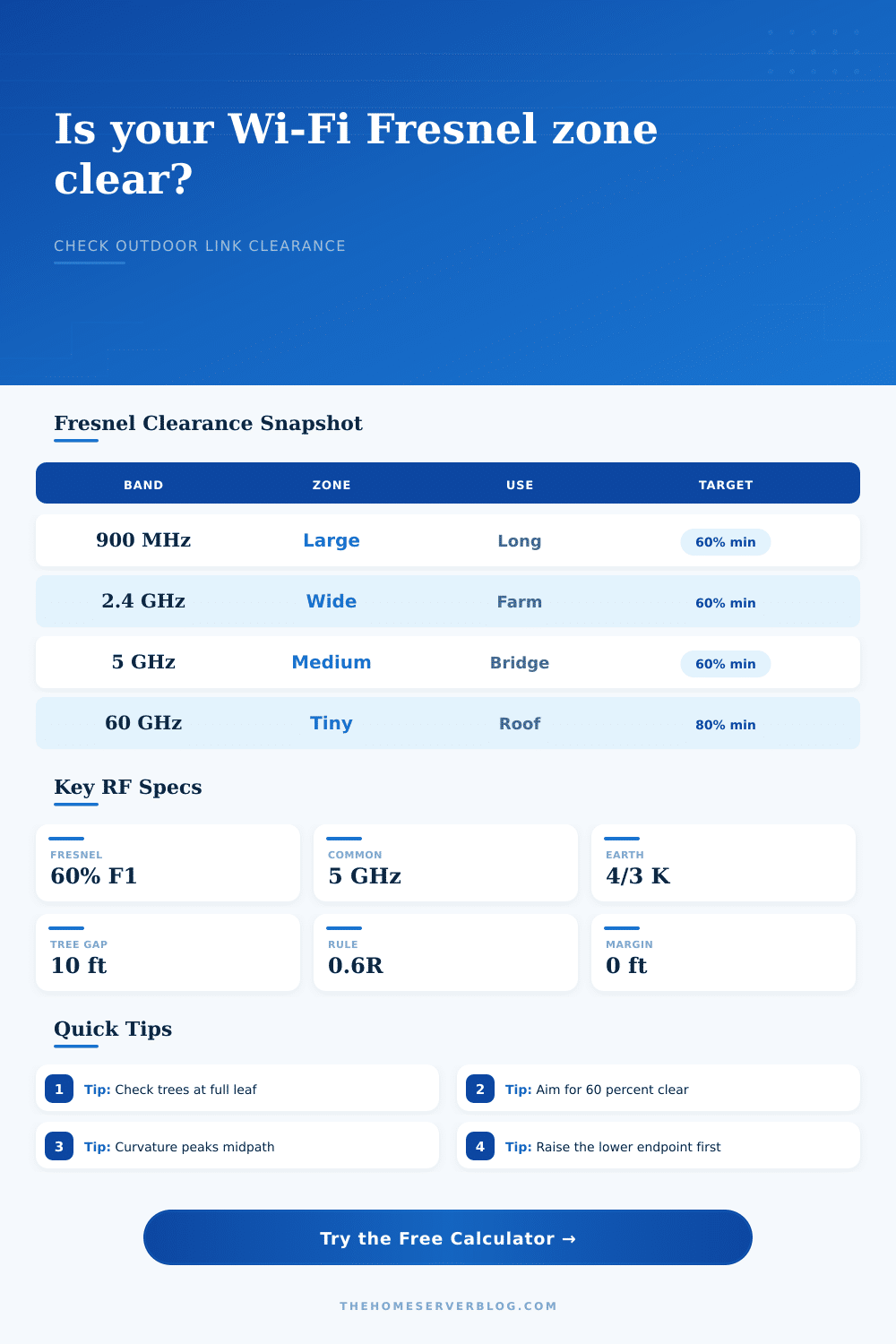
| 900 MHz | Telemetry, rural sensors, low-rate links | Largest first-zone radius | Needs the most vertical room around trees and ridges. |
| 2.4 GHz | Farm bridge, older outdoor mesh | Broad Fresnel zone | Good foliage tolerance is limited if the zone is clipped. |
| 5 GHz | Home lab bridge, WISP CPE, cameras | Moderate first-zone radius | Often the practical balance of height and throughput. |
| 6 GHz | Short clean campus or yard links | Slightly smaller than 5 GHz | Great when local rules and clients support the band. |
| 60 GHz | Short rooftop high-capacity links | Very small Fresnel zone | Fresnel is easier, but aim, rain, and blockage are stricter. |
| Clearance target | Use case | Risk if lower | Calculator setting |
|---|---|---|---|
| 40 percent | Rough feasibility check | Higher diffraction loss and unstable MCS. | Only for early scouting, not final mast sizing. |
| 60 percent | Common fixed wireless planning | Normally acceptable if fade margin is healthy. | Default for Wi-Fi bridges and WISP-style paths. |
| 80 percent | High-capacity or 60 GHz path | Less tolerance for survey error and movement. | Use where peak throughput and low retries matter. |
| 100 percent | Conservative engineering envelope | May demand tall masts on long low-band links. | Useful for comparing worst-case clearance. |
| Obstacle type | How to measure | Suggested margin | Field note |
|---|---|---|---|
| Tree line | Use mature canopy height at full leaf. | 5 to 15 ft / 1.5 to 4.5 m | Growth and wind movement can erase a thin margin. |
| Roof ridge | Measure ridge height relative to each endpoint ground. | 2 to 6 ft / 0.6 to 1.8 m | Include mounts, chimneys, and seasonal equipment. |
| Hill or berm | Use map elevation plus local object height. | 5 to 20 ft / 1.5 to 6 m | Curvature and terrain uncertainty stack together. |
| Pole or utility line | Measure top obstruction, not just the crossarm. | 3 to 8 ft / 0.9 to 2.4 m | Keep safety clearances separate from RF clearance. |
6Practical Fresnel tips
It’s the best situation: from the base of a tower you gaze over a half-mile distance into the eyes of a barn roof. There is no power lines. There are no trees. Just you and your other antenna. It seems ideal. So you crank up the link. And it crawls. The dashboard show good signal strength. But the data throughput stinks.
Here’s the deal: It has nothing to do with line-of-sight. It has everything to do with what surrounds that line. Wi-Fi doesn’t shoot out as a tight little laser beam. Instead, it spreads like the waist of an hourglass, narrowing at both ends while fattening in the center.
Why Clear Line of Sight Is Not Enough
That blurry belly is called first Fresnel zone. Anything that intrude on this area causes radio waves to ricochet off it arriving out of phase, canceling out the direct signal. It is a physics problem, not a hardware issue.
When most folks plan outdoor bridges they do it based off solely on what can be seen from A to B. But visual line of sight does not consider the actual 3D space which the signal pass through. Once you enter your antenna heights, frequency and path length the math is handled by the calculator. There’s no more guessing on which conversions or coefficients to use.
Enter those approximate measurements and let the tool tells you precisely how far apart your signal path must be from the obstruction. Frequency is important too because lower bands such as 900 MHz produce enormous, bloated zones that is difficult to maintain clearance. On the other hand higher bands such as 60 GHz constrict into a tiny needle-like zone.
Then there is the Earth, itself. Your signal doesn’t exist only above the surface, the earth curves away beneath it. That sag becomes significant over a mile. The tool makes up for this bulging with a standard refraction factor so your height estimates aren’t overly hopeful fantasies.
Where is the obstruction located? For example, a small tree 10′ tall close by may work. But that same tree smack dab in the middle of the link… no bueno. The Fresnel zone is thickest along the middle. Where it’s needed most: that’s where you have to maintain clearance.
And that means knowing if you’re cutting into that zone when your path drops down into a dip, or crosses a row of oak trees. That’s where the reference table on the page comes in. It explains how various bands perform under different conditions. It can help you visualize why a 6 GHz link may require a taller mast then a 5 GHz link, across the exact same distance. It’s not simply raw power; it’s geometry.
Live things also block signals: remember the trees? They get bigger. Their leaves gets fuller in the summer. The wind pushes their branches around. Give yourself some room. Engineers usually try for a 60% buffer zone. That’s where they say you should of had at least sixty percent of the zone cleared out. Sixty percent of the radius of the zone.
I call it a rule of thumb; it’s a good rule of thumb. Go any lower than that and you’re asking for trouble with your signal getting lost or interfered with. Go up above that and you have room for equipment drift or bad weather. The calculator tells you how much space you have. If it’s a negative, something block it.
Trim a tree limb, move an endpoint, or lift antenna. Theory meets dirt in the site survey. Should you tape measure it? Sure. But what about the cable run? What about the antenna mount? Is there a flexible mast involved? And don’t forget, add a few feet of terrain margin to all your inputs. That’s cheap insurance.
Reality is a messy RF thing. The ground isn’t flat. The horizon isn’t straight. Your task is to model just enough of that reality to make it work. Use the presets for a baseline; tweak the variables to match your real site. Check the results mid-way through and at any obvious obstructions.
A solid wireless bridge isn’t about spending money on the most expensive stuff; it’s about understanding the physics of what your devices are trying to do across the gap in the air. Even with a large worth of furnitures, all those devices won’t work if you don’t treat the area surrounding the beam like a no-man’s land.
Clear the zone, give some breathing room to the trees, and honor the curvature. The signal will flow. Your narrow waist stays unobstructed. You observed a clear line of sight from the ground. It works now.